About the IS200BPIRG1A
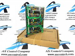
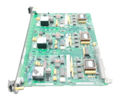
As a Digital Interface Board, the IS200BPIRG1A is used within Innovation Medium Voltage--GP, Type H drives. This board provides a digital bus interface of 15V to 5V between the Bridge Interface card (BICR) and the Fiber Optic Hub card (FOHB.) The IS200BPIRG1A is built with:
- two board connectors
- a backplane connector, marked P1
- a second connector marked PLO
- a transistor
- one relay
- several resistors and capacitors
- six integrated circuits
Any capacitor, transistor, resistor, diode, or even specialized integrated circuit made available to the base printed circuit board of this IS200BPIRG1A printed circuit board product offering should exist as part of a greater voltage limitation and suppressions strategy seemingly standardized to GE's Mark product series suite. The P1 connector on this board may need a custom extender board in order to access individual pin signals. The PLO Connector is a 50-pin ribbon connector that lnks the Digital Interface card with the Fiber Optic Hub card.
IS200BPIRG1A Device Connector Tips and Specifications
Each one of this IS200BPIRG1A component circuit board's crucial connectors are listed in the IS200BPIRG1A Datasheet attached above in our handy manuals tab for your ease of research; some of these connectors include the DCOM digital common connector, the NC not connected connector, the ACOM analog common connector, and many more less self-explanatory connectors, again as described above. This IS200BPIRG1A PCB's specific connectors are not the only hardware element listed in detail in its pertinent original instructional materials. as they also make mention of four testpoints in this IS200BPIRG1A product's normal Mark VI Turbine Control System Series assembly, including the:
- TP1 REFA Analog Phase A Reference Signal Testpoint
- TP2 REFB Analog Phase B Reference Signal Testpoint
- TP3 REFB Analog Phase C Reference Signal Testpoint
- TP4 ACOM Analog Reference Common Testpoint