❮


❯


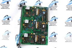
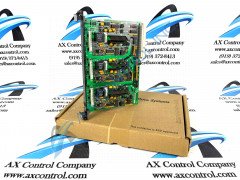
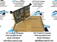
IS200BPIBG1A
- 4.87 (15)
The IS200BPIBG1A Phase Logic Module/ IGBT Drive Personality Interface
AX Control Warranty Info
All products we sell are backed by our unparalleled warranty. A warranty certificate will be provided with your order upon request.
| All PLCs, HMIs, and Turbine Control Boards: | 3 Years |
| All AC/DC and Servo Drives: | 2 Years |
| All Motors: | 1 Year |
IS200BPIBG1A Manuals, White Papers, Data Sheets, and Troubleshooting
- IS200BPIBG IGBT Drive Bridge Personality Interface Board GEI-100266.pdf
- IS200BPIBG GEI-100266 IGBT Drive Bridge Personality Interface Board Introduction.pdf
- IS200BPIBG Drive Brige Personality Interface Board App Data.pdf
- IS200BPIBG Drive Brige Personality Interface Board Renewal and Replacement.pdf
- IS200BPIBG Drive Brige Personality Interface Board Layout Diagrams.pdf


You may also like...