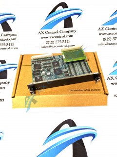
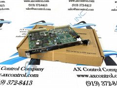
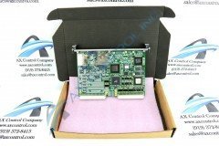
About the IS200VCCCH1BBC
As a Discrete Input Output board or DIO for short, the VCCC board will control up to four contact relay outputs as well as termination boards depending on the rack that the model has been installed. In addition to these contact relay outputs, the VCCC accepts:
- 48 discrete outputs
- 24 relay outputs
- typical digital inputs in the range of forty-eight while
- digital outputs in the range of twenty-four
- capacitors
- resistors
- DC power supplies
- test points
- different connector types
- vertical pin connectors
- backplane connectors
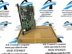
If you are holding the VCCC board with the faceplate facing you, you will notice that there is a daughterboard located in the upper right-hand corner. This daughterboard, although sometimes revised or replaced, can be defined as the TRLYH1B daughterboard, and houses twelve magnetic plug-in relays.
IS200VCCCH1BBC Board Voltage Suppression Specifications
Another additional visual feature of the IS200 VCCC is the Discrete Input/Output Board's three LEDs on the front faceplate labeled run, status, and fail. The face plate's RUN led flashed green to indicate a normal drive assembly running condition. VCCC's FAIL led glows solid red when a functional failure of the VCCC within the greater drive assembly is detected. The final LED is usually a non-factor, but displays a steady orange color when a diagnostic alarm condition is discovered by the IS200VCCCH1BBC. Integrated chips also make up a main portion of the IS200VCCCH1BBC board. There are sixty of these chips which are labeled:
- SRAM
- FGPA
- CMOS static RAM
There are also two plugs that are used to cable two other terminal boards in the Mark VI System. The two boards that are cabled to the VCCC model are the aforementioned TRLY PCB and the TICI component board. Please note that the two boards cabled to the VCCC model are referred to as barrier-type termination boards in the GER-4193A Speedtronic Mark VI Turbine Control System Manual. This IS200VCCCH1BBC PCB has a three-fold revision table.