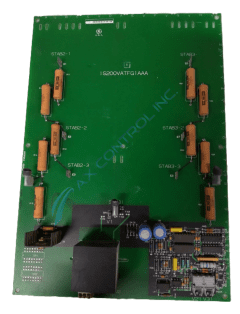
About the IS200VATFG1AAA
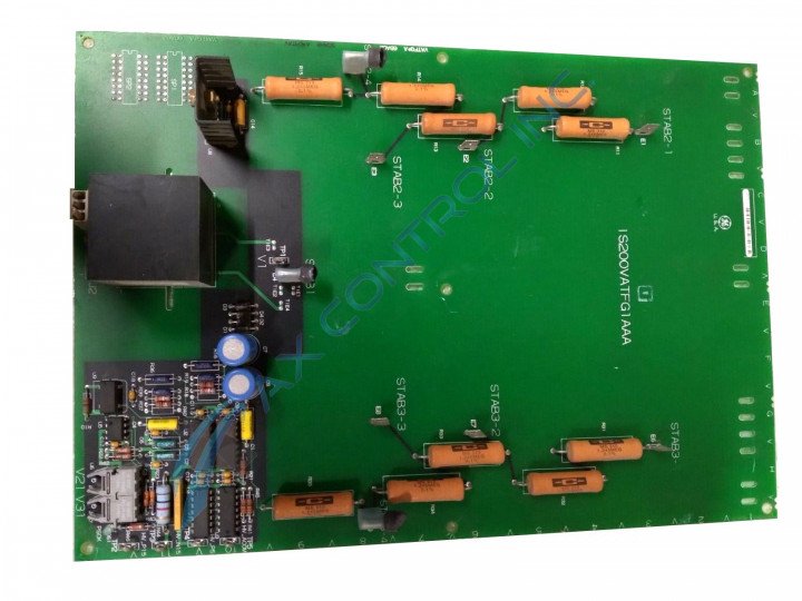
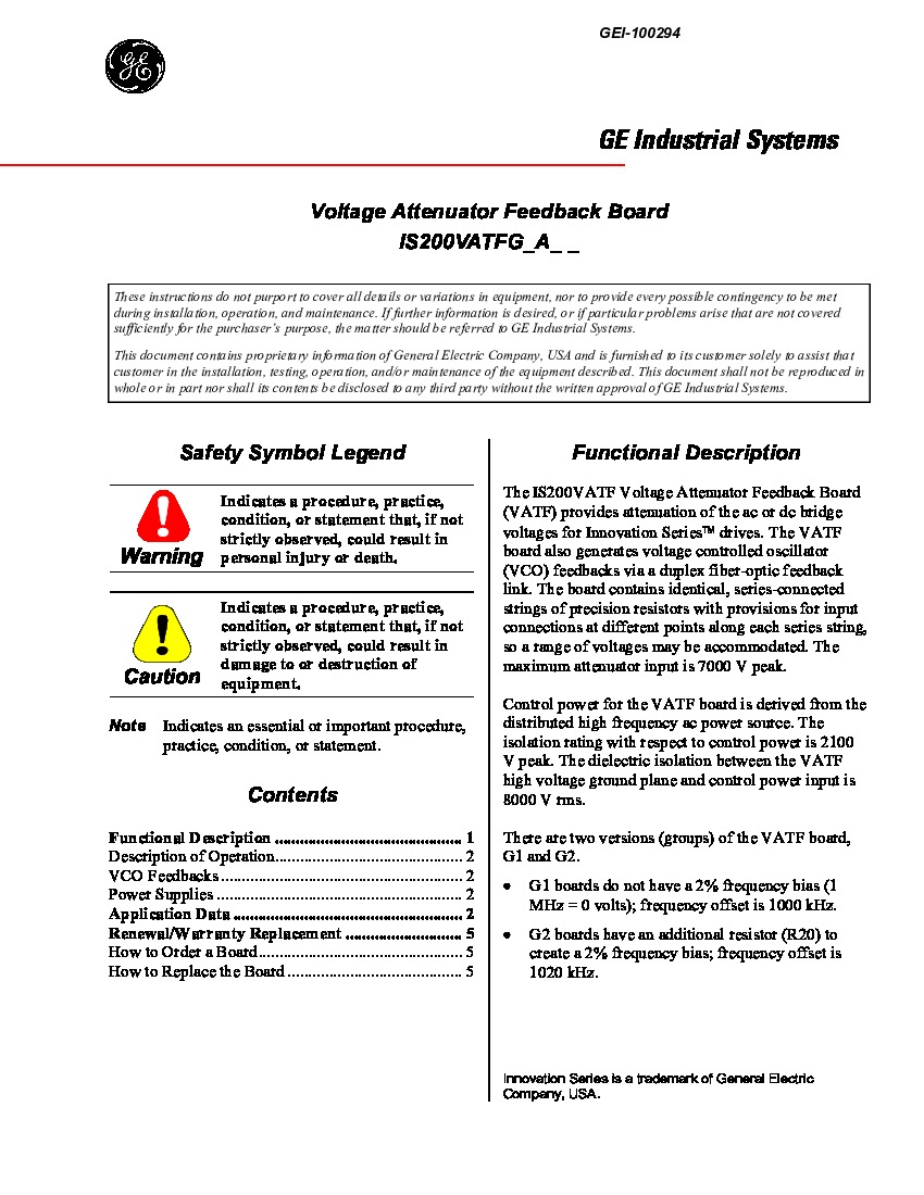
The board achieves attenuation through two sets of identical strings of series-connected precision resistors with input connections (stab-on connectors) at places along the string to allow for the accommodation of a range of voltages. The control power for this model is derived from the distributed high-frequency AC power source. The IS200VATFG1AAA board has dielectric isolation; this isolation is between the VATF high voltage ground plane and the control power, the input for this isolation is 8000 V rms. The IS200VATFG1AAA is built with:
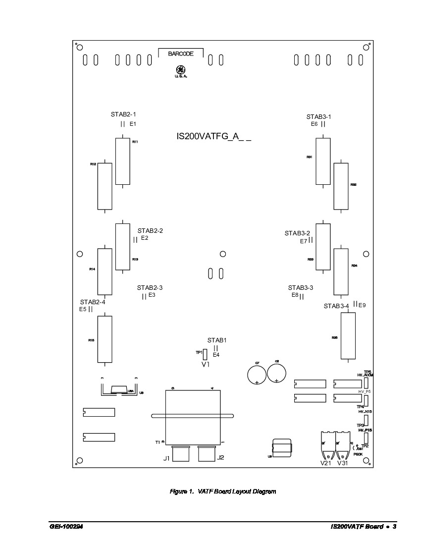
- eight stab-on connectors
- two fiber-optic transmitter connectors
- five TP test points
- two plug connectors
- one LED indicator (PSOK.)
- single transformer
- one heat sink component
- several integrated circuits
- electrolytic, ceramic, and polyvinyl capacitors
- a single resistor network array
IS200VATFG1AAA Voltage Suppression and Testpoint Information
When the IS200VATFG1AAA model is being operated it will accept three-phase AC input voltages. Two of the three phases, specifically phases two and three of the input will be applied to two identical precisions resistors to reduce high voltages to signal electronic levels. The electronic levels are related to phase one. Phase one of the VATF board directly connects to the high-voltage ground plane. One of the alternative features of the VATF board is that it can measure the two DC rail voltages relative to the DC neutral or midpoint. This IS200VATFG1AAA product is something of a well diagnostically-supported GE Mark Series product offering, as its offered with a series of relevant test points. Some of the specific test points afforded to this IS200VATFG1AAA product's normal Mark VI Series assembly include its
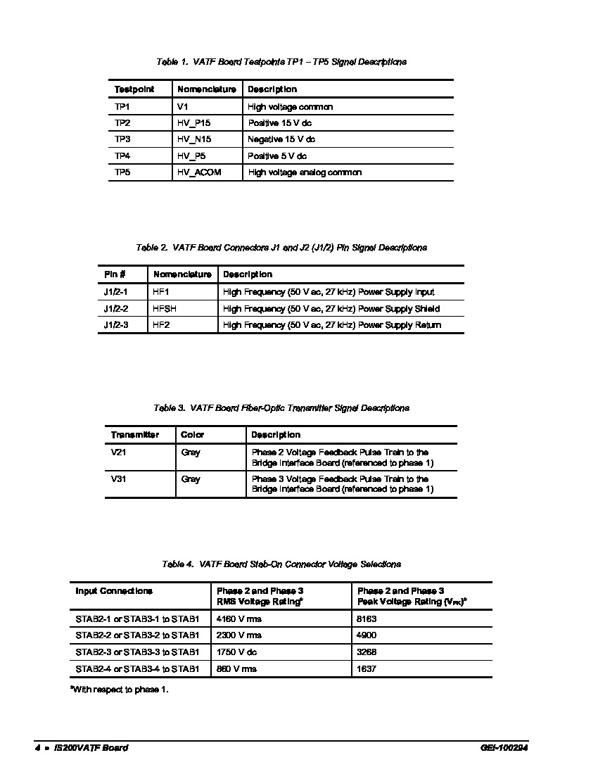
- V1 TP1 High voltage common testpoint
- HV_P15 TP2 Positive 15 V dc testpoint
- HV_N15 TP3 Negative 15 V dc testpoint
- HV_P5 TP4 :Positive 5 V dc testpoint
- HV_ACOM TP4 High voltage analog common testpoint


