About the IS200PICHG1A
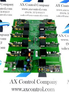
The IS200PICHG1A works within the Innovation Series drives. The board includes all of the feedback signal processing circuits and gating drivers needed for four dual IGBT modules of the H-bridge phase assembly. This IS200PICHG1A Phase Interface Control Board printed circuit board product offering's normal style of Mark VI Series assembly features several components that are identifiable as interfaces. Each one of these interfaces exists as a fiber optic interface, with each interface being guaranteed their own individual fiber optic isolators per each gating or feedback circuit. Two total logic ground planes are available in the assembly of this IS200PICHG1A Phase Interface Control Board PICH-abbreviated product offering. This board has thirteen daughter boards that are soldered onto the primary. Included in the thirteen are:
- Eight IGBT Driver Boards (IS205IGDH)
- Four VCO Feedback Transmitter Boards (IS205VCXH)
- One IGBT Temp Feedback Board (IS205TFBH)
Non-PCB IS200PICHG1A Hardware
Each one of the four total VCO Feedback Transmitter Boards in this IS200PICHG1A Phase Interface Control Board device's normal Mark VI Series assembly is equipped with their own functionality, again as detailed in the IS200PICHG1A Phase Interface Control Board instructional manual made available to our manuals tab above for your convenience of research. Two of this IS200PICHG1A Phase Interface Control Board product's four VCO Boards are utilized for in DC Capacitor Bus Voltage processes, while one is used for Phase to Neutral Voltage Conversion and the final remaining PCB in Phase Current. This IS200PICHG1A Phase Interface Control Board device's above-attached manual materials details several significant functional faults that impact this IS200PICHG1A Phase Interface Control Board device disproportionately. The IS200PICHG1A board includes as well:
- 3 LEDs
- 1 jumper switch
- 15 TP test points
- 12 plug connectors
- 3 stab-on connectors
- 24 fiber optic connectors
- high-voltage capacitors
- heat sinks
- inductor coils
- transformers
- 2 logic area ground planes
- a power ground (SHCOM)
- a signal ground (DCOM.)
- Logic circuits supplied by the +5V are referenced to this signal ground