In Stock
DRIVE DSP CONTROL BOARD GENERAL ELECTRIC | Image
3 year warranty

DRIVE DSP CONTROL BOARD GENERAL ELECTRIC | Image
DRIVE DSP CONTROL BOARD GENERAL ELECTRIC - Wiring Diagram Image

IS200DSPXH2C

    Varying star amount pictures Varying star amount pictures Varying star amount pictures Varying star amount pictures Varying star amount pictures
  • 5.00 (3)
  • Click a star to rate this product
    Varying star amount pictures Varying star amount pictures Varying star amount pictures Varying star amount pictures Varying star amount pictures
  • 5.00 (3)
  • Click a star to rate this product
GE Mark VI Board IS200DSPXH2C

AVAILABILITY:

IN STOCK
SHIPS IN 3-5 DAYS

Sell Surplus: Have a IS200DSPXH2C to sell? Sell Now
Exchange Credit: Learn more about our exchange credit program
  • Part Number: IS200DSPXH2C
  • SKU: IS200DSPXH2CGBTC
  • Manufacturer: GE Boards & Turbine Control
  • Series: Mark VI IS200

Product Description

The IS200DSPXH2C is what is called a drive DSP control board. This is a form of printed circuit board or PCB created by General Electric for the Mark VI series. The Mark VI is the most recent series in the Mark family of equipment which controls the functions of gas and steam turbines.

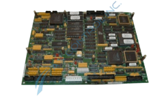
The IS200DSPXH2C is a relatively large printed circuit board. On the left edge of the IS200DSPXH2C is a long metal piece which spans the length of the border. To the right of the IS200DSPXH2C, there is a silver metal component which is shaped like a square. The part number of this capacitor is printed on the top in black writing. The most prominent components on the IS200DSPXH2C are two (2) large square components which are black. These square components are paired together in the center of the IS200DSPXH2C. Sitting between these two (2) large components are two long slim components known as a resistor network. A resistor network is a component which houses a series of resistors which are lined up. The total resistance of each resistor network is the same as the sum of the resistors located inside. These resistors networks are white in color. Five (5) more resistor networks have been placed around the IS200DSPXH2C. One of these is positioned horizontally right below the large black component on the left. The remaining four (4) resistor networks may be seen to the right of the black component on the right. A variety of several other capacitors are featured on the IS200DSPXH2C. Two (2) of these are solid yellow and rectangular and several others are very small and made of silver metal.

Reviews For IS200DSPXH2C

Internal Review
(5.0)

This board uses a marker pulse to latch or reset the up/down counter. This is part of one of the board's two quadrature incremental tach interfaces. Signals drive two 16-bit up/down counters. Read through associated manuals for additional information about marker pulse and up/down counters. --AX Control Tech Team.

Repair Services For IS200DSPXH2C

Type Lead Time Price Action
Repair Service 1-2 weeks $700

Our highly skilled technicians can repair your IS200DSPXH2C. All of our repairs come with a 3 Year AX Control Warranty. Please contact us for additional information about our repair process. To receive the repair pricing and lead time listed above please process your repair order via our website. The following repair options may be available upon request:

  • 48-72hr Rush Repair
  • Detailed Repair Reports
  • AX Control Certificate of Warranty

AX Control Warranty Info

All products we sell are backed by our unparalleled warranty. A warranty certificate will be provided with your order upon request.
All PLCs, HMIs, and Turbine Control Boards: 3 Years
All AC/DC and Servo Drives: 2 Years
All Motors: 1 Year
Learn More