About the IS200TRLYH1BEC
Diagnostic Hardware Tips and Specifications
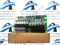
The IS200TRLYH1BEC is a rectangular circuit board with a number of various components ranging from large to small. The left edge of the IS200TRLYH1BEC is occupied by a pair of two (2) large terminal blocks. These terminal blocks are solid black and they contain twenty-four silver metal terminals each. The terminals are labeled with numbers from one (1) to twenty-four (24) and twenty-five (25) to forty-eight in white printing. To the right of the terminal blocks are a series of transformers that are tall and rectangular in shape. They are silver and black and have been covered with transparent plastic.
There are twelve (12) of these transformers on the board in total. As is indicated in the IS200TRLYH1BEC instructional manual made available above, this IS200TRLYH1BEC device's various functional fault and diagnostic functioning conditions are indicated through a series of LED indicators, with each indicator light being accompanied by their own factory-printed nomenclature labels. Some of this IS200TRLYH1BEC product's specific LEDs include its:
- RUN flashing green LED indicator
- FAIL solid red LED indicator
- Orange LED indicator
Additional IS200TRLYH1BEC Device Hardware Information
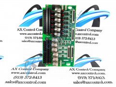
This IS200TRLYH1BEC product's RUN indicator flashes verde during normative functionality of the IS200TRLYH1BEC product, while its self-explanatory FAIL LED is only glowing bright red when a fatal functional fault is detected. The third LED is orange and glowing to demonstrate non-fatal functional fault conditions. The six (6) transformers grouped on the top half of the IS200TRLYH1BEC are surrounded by a series of components, like its:
- Six (6) circular black transistors
- Circular red MOV or metal oxide varistors paired together with each transistor
- Six (6) blue capacitors aligned to the right of the IS200TRLYH1BEC.
- Two white connectors sitting at the top edge
- these connectors each contain three small ports
Another one (1) of these white connectors are placed at the lower edge of the IS200TRLYH1BEC. This connector features a series of four (4) ports. The IS200TRLYH1BEC contains many small integrated circuits positioned all around the circuit board.
According to this IS200TRLYH1BEC device's originally-produced instructional manual materials made available in large part to our convenient manuals tab above, this IS200TRLYH1BEC printed circuit board or PCB for short is actually not the originally designed and developed device of its specific Mark VI Turbine Control System Series functionality. That can be considered the IS200TRLYH1 parent product notably not utilizing this IS200TRLYH1BEC device's three-fold significant revision history.