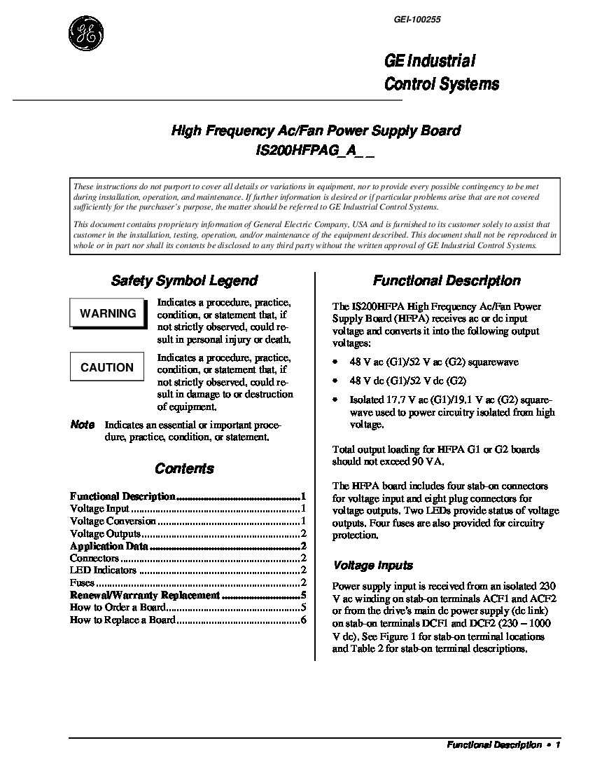
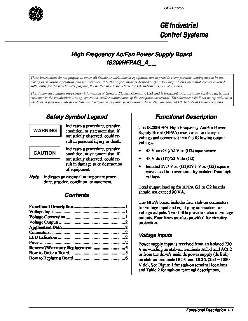
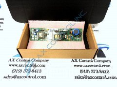
About the IS200HFPAG1ADB
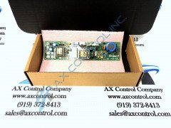
The IS200HFPAG1ADB receives dc or ac inputs and converts them into outputs to run the Fan or other power supplies. The outputs from this board are 48 VDC, 48 VAC square wave, or Isolated 17.7 VAC square wave that has been designed for power circuitry. The IS200HFPAG1ADB is built with:
- diodes, resistors, and capacitors made from a wide variety of materials
- two transformers on its surface
- each with at least one heat sink
- four fuses
- four stab-on connectors for inputs
- eight plug connectors for outputs
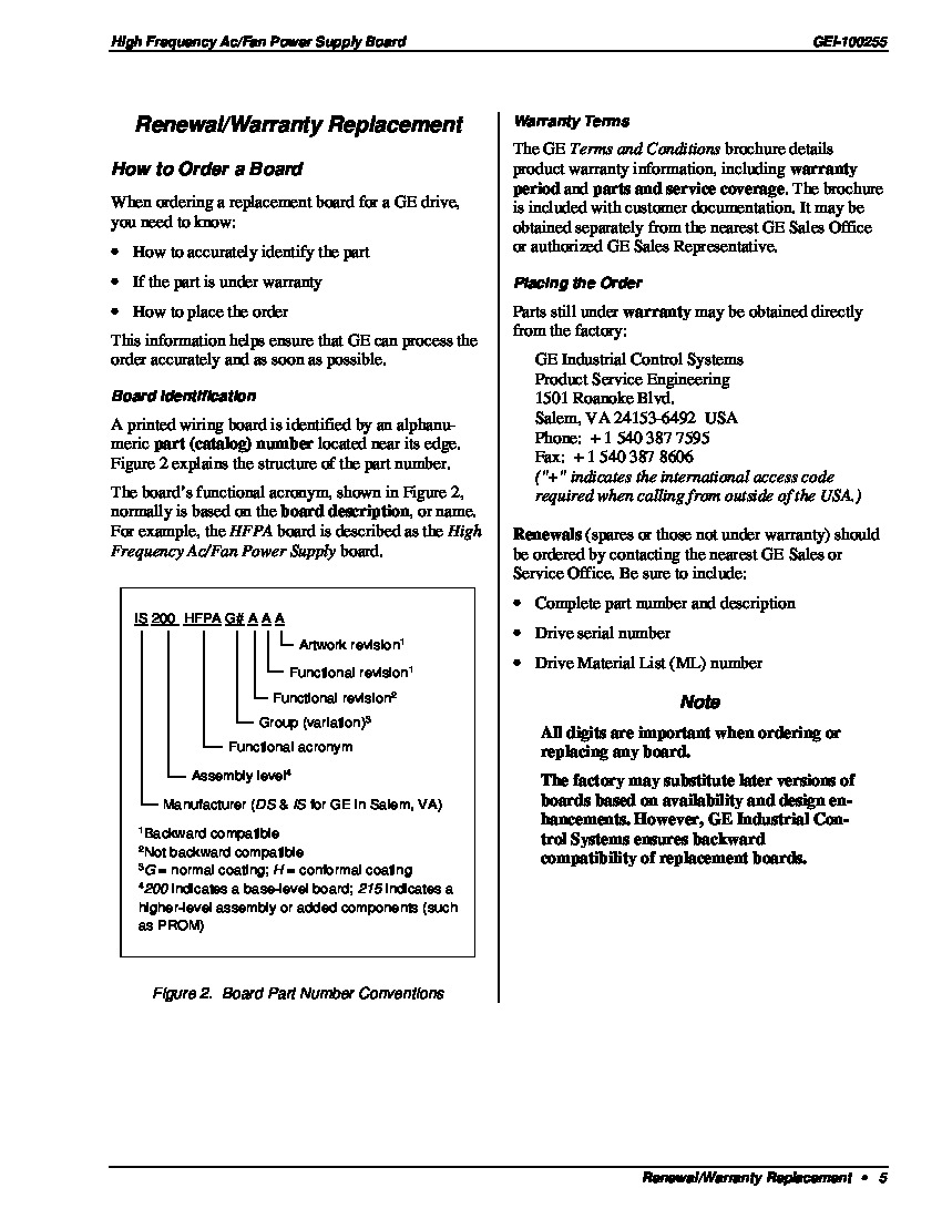
The IS200HFPAG1ADB also has two LED indicators that allow users to easily see when circuits are powered up. These are labeled DS1 and DS2. The IS200HFPAG1ADB should only be removed, inserted, or adjusted when all power is removed from equipment. For detailed information about removal or replacement, please refer to datasheets or manuals from GE. If you no longer have access to these documents, AX Control may be able to include replacements with your order.
IS200HFPAG1ADB Diagnostic Hardware
This IS200HFPAG1ADB device' LED indicator lights both indicate their own separate diagnostic readings, with each of these indicators being accompanied by their own factory-printed nomenclature label for convenient identification purposes. In terms of LED purposes:
- This IS200HFPAG1ADB device's DS1-labeled LED indicator is activated or ON when the 17.7/19.1 V ac output in the HFPA-abbreviated printed circuit board's normal assembly is functioning normally
- If this this DS1-labeled LED is OFF, one must check on the fuse FU4 for potential blows
- This device's DS2-labeled LED DS2 is turned ON when its 48/52 V ac and dc output is OK/normal
- If DS2 is off, it is critical to check that the FU1 fuse is not blown at all
Both of this High-Frequency Ac/Fan power supply card's two LED indicators are included on its side-mounted metallic VME installation faceplate.


