About the IS200DSPXH1BCA
The Mark VI Series that this IS200DSPXH1BCA Digital Signal Processor Board belongs to, as you may have been able to guess based off of its full extended Mark product series name alone, is pertinent to a specific series of possible functional applications in the management systems and control systems of General Electric-compatible gas, wind, and steam turbine automated drive assemblies. This does actually happen to represent quite an upgrade upon the similarly-named Mark V Turbine Control System Series that immediately preceded this IS200DSPXH1BCA Digital Signal Processor Board product's Mark VI Series, as the Mark V Series only possesses potential gas and steam-sequestered functional setting applications.
IS200DSPXH1BCA Hardware Tips and Specifications
The IS200DSPXH1BCA is primarily used to control the motor regulator and bridge regulator but can also be used for gating functions and generator field control applications. It has processing power, logic functions, and interfacing capabilities. The board is designed to perform custom logic functions using a high-performance digital signal processor and application-specific circuits. This IS200DSPXH1BCA Digital Signal Processor Board product offering within the Mark VI Turbine Control System Series is something of an atypical Mark VI Series product; given the fact that its original General Electric-formulated instructional manual materials are largely intact online for the purposes of this IS200DSPXH1BCA Digital Signal Processor Board personalized product page here. These materials dictate three styles of onboard firmware stored in this IS200DSPXH1BCA Digital Signal Processor Board product's flash memory. These firmware styles include:
- Boot Loader Firmware
- Application Code Firmware
- Configuration, Excitation, and Drive Parameter Firmware
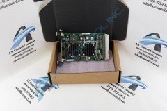
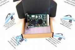
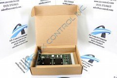
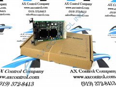
The IS200DSPXH1BCA is designed with an attached front faceplate. This has embedded in its surface two LED indicators labeled “Status” and “Fault” as well as two Input/Output ports. The I/O ports are the DSP emulator port (P5) and the engineering monitor port (P6.) The board also has a backplane connector (P1) located on the opposite short board edge, as well as a vertical pin connector (P7) that is usually only used during board development. There are two test points on this model, P6 and P7; these test points are only used for development and testing. Using the P6 and P7 test points outside of their intended usage could cause issues in the board operation.