In Stock
531X111PSHALG1 Image One
3 year warranty

531X111PSHALG1 Image 1
531X111PSHALG1 Image 2
531X111PSHALG1 Image 3
531X111PSHALG1 Image 4

531X111PSHALG1

    Varying star amount pictures Varying star amount pictures Varying star amount pictures Varying star amount pictures Varying star amount pictures
  • 5.00 (4)
  • Click a star to rate this product
    Varying star amount pictures Varying star amount pictures Varying star amount pictures Varying star amount pictures Varying star amount pictures
  • 5.00 (4)
  • Click a star to rate this product
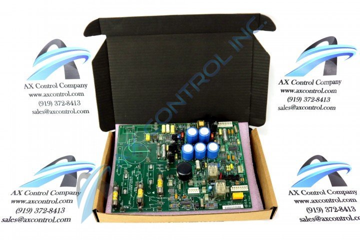
GE Motor Field Control/Power Supply 531X111PSHALG1

AVAILABILITY:

IN STOCK
SHIPS TODAY

Sell Surplus: Have a 531X111PSHALG1 to sell? Sell Now
Exchange Credit: Learn more about our exchange credit program
  • Part Number: 531X111PSHALG1
  • SKU: 531X111PSHALG1GBTC
  • Manufacturer: GE Boards & Turbine Control
  • Series: 531x Boards

Product Description

The GE Terminal Board Relay Card 531X111PSHALG1 supplies the 5 V dc, 15 V dc, and 24 V dc current used by the drive. It also features the pulse transformer for the motor field circuitry. The GE Terminal Board Relay Card 531X111PSHALG1 also includes the 3TB assembly which is attached to a metal surface in the drive. The assembly is connected to the 531X111PSHALG1 through three wires that you must disconnect from the defective assembly and reconnect when the replacement assembly is installed.

A ribbon cable connects to the assembly that also must be disconnected. Grasp the ribbon cable from the connector and use your other hand to steady the assembly. Pull the ribbon cable out and move it to one side away from the working area.

Use a screwdriver to remove the five screws that attach the assembly to the mounting surface and also remove the screws from the support posts. Set the screws aside for use in securing the replacement assembly. If any of the screws fall into the drive and lodge in the components you must locate and remove them from the drive. Use a vacuum hose attachment to clean the area.

Position the replacement assembly and mark where to drill holes for the installation. Use a drill to make holes for the screws. Then, insert the screws and tighten them to secure the assembly. Connect the three wires to the 531X111PSHALG1 and insert them into connectors MOV1, MOV2, and MOV3. Route the three wires before you connect them to the board.


Repair Services For 531X111PSHALG1

Type Lead Time Price Action
Repair Service 1-2 weeks $577

Our highly skilled technicians can repair your 531X111PSHALG1. All of our repairs come with a 3 Year AX Control Warranty. Please contact us for additional information about our repair process. To receive the repair pricing and lead time listed above please process your repair order via our website. The following repair options may be available upon request:

  • 48-72hr Rush Repair
  • Detailed Repair Reports
  • AX Control Certificate of Warranty

AX Control Warranty Info

All products we sell are backed by our unparalleled warranty. A warranty certificate will be provided with your order upon request.
All PLCs, HMIs, and Turbine Control Boards: 3 Years
All AC/DC and Servo Drives: 2 Years
All Motors: 1 Year
Learn More