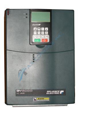
6V41-027TA

    Varying star amount pictures Varying star amount pictures Varying star amount pictures Varying star amount pictures Varying star amount pictures
  • 4.75 (4)
  • Click a star to rate this product
    Varying star amount pictures Varying star amount pictures Varying star amount pictures Varying star amount pictures Varying star amount pictures
  • 4.75 (4)
  • Click a star to rate this product
The 6V41-027TA 20 HP Inverter Drive

AVAILABILITY:

IN STOCK
SHIPS TODAY

Sell Surplus: Have a 6V41-027TA to sell? Sell Now
Exchange Credit: Learn more about our exchange credit program
  • Part Number: 6V41-027TA
  • SKU: RE-9858
  • Manufacturer: Reliance Electric
  • Series: GV6000 Drives

6V41-027TA Technical Specifications

Manufacturer Reliance Electric
Series GV6000
Part Number 6V41-027TA
HP 20 HP
Input Voltage 460 VAC
Enclosure NEMA 1 Air Cooled
Digital Input Voltage 24 VDC
Braking Transistor Included
Labeling UL Listed, IEC Certified

About the 6V41-027TA

6V41-027TA is a GV6000 AC Drive that is manufactured by Reliance Electric. The nominal duty horsepower is 20, the continuous amps are 27, and the frame is 2. The dimensions of frame 2 are 222 mm x 342.5 mm x 200 mm x 192 mm x 320 mm. This drive has:

  • a 460 VAC input
  • a NEMA 1 enclosure
  • a braking transistor
  • 24 VDC I/O rating

6V41-027TA 20 HP Inverter Drive Alarm Values

The various alarms integrated into this 6V41-027TA 20 HP Inverter Drive device all have different reference indicators and functions as follows:

  1. Alarm number 5 is an analog input loss
  2. Alarm number 20 is a bipolar conflict
  3. Alarm number 32 is a brake slipped fault
  4. Alarm number 10 is a deceleration inhibit fault
  5. Alarms 17-19 are digital input conflicts
  6. Alarms 8-9 are drive overload levels
  7. Alarm number 26 is a flux amps reference range fault
  8. Alarm number 15 is a ground warning
  9. Alarm number 34 is a home not set fault
  10. Alarm number 13 is an input phase loss
  11. Alarm number 25 is an IR volts range fault
  12. Alarm number 14 is a load loss fault
  13. Alarm number 23 is a maximum frequency conflict
  14. Alarm number 12 is a motor thermistor fault
  15. Alarm number 21 is a motor type conflict
  16. Alarm number 22 is an NP Hz conflict
  17. Alarm number 3 is a power loss fault
  18. Alarm number 1 is a precharge active fault
  19. Alarm number 50 is a prof step conflict
  20. Alarm number 31 is a PTC conflict
  21. Alarm number 29 is a sleep configuration error
  22. Alarm number 27 is a speed reference conflict
  23. Alarm number 4 is a start at power up alarm
  24. Alarm number 30 is a TB man reference conflict
  25. Alarm number 49 is a torqueprove conflict
  26. Alarm number 2 is an undervoltage fault
  27. Alarm number 24 is a VHz negative slope
  28. Alarm number 11 is a waking timer error

Frequently Asked Questions about 6V41-027TA

What size frame does a GV6000 6V41-027TA have?
A 6V41-027TA has a size 2 frame according to the GV6000 AC Drive User Manual. 
What is the motor-operated potentiometer function on a 6V41-027TA?
The MOP function on a 6V41-027TA uses digital inputs to increment or decrement the speed reference on a 6V41-027TA at a programmed rate. The MOP function on a 6V41-027TA GV6000 has the following components:
-MOP Frequency parameter
-MOP Rate parameter
-Save MOP Ref parameter
-MOP increment input parameters 361 to 366
-MOP decrement input parameters 361 to 366
Where can I find a visual aid to help me locate terminal block locations on a 6V41-027TA?
The GV6000 AC Drive User Manual has a diagram in section 2.5 of the manual that shows where power terminal blocks are in frame sizes 1-6. A 6V41-027TA has three power terminal block locations according to the diagram in the manual and because the manual previously identifies 6V41-027TA as having a size 2 frame. The diagram in the manual displays where the power terminal blocks are on a 6V41-027TA or any GV6000 drive with a 2 frame size.
What is the difference between alarms and faults on a 6V41-027TA?
GV6000 6V41-027TA drives have both alarms and faults. Alarms on a 6V41-027TA indicate conditions that may affect drive operation or application performance on your 6V41-027TA. Faults are errors on your 6V41-027TA that need immediate attention. User-configurable alarms can often lead to a fault condition on a 6V41-027TA if left untreated. GV6000 drives also have specific alarm status parameters along with separate fault code errors. View the manual for alarm descriptions and fault code descriptions on a 6V41-027TA.
Where can I find a manual for my 6V41-027TA?
AX Control will send you a link to the GV6000 AC Drive User Manual upon request to help you with your 6V41-027TA.

Repair Services For 6V41-027TA

Type Lead Time Price Action
Repair Service 1-2 weeks $2014

Our highly skilled technicians can repair your 6V41-027TA. All of our repairs come with a 3 Year AX Control Warranty. Please contact us for additional information about our repair process. To receive the repair pricing and lead time listed above please process your repair order via our website. The following repair options may be available upon request:

  • 48-72hr Rush Repair
  • Detailed Repair Reports
  • AX Control Certificate of Warranty

AX Control Warranty Info

All products we sell are backed by our unparalleled warranty. A warranty certificate will be provided with your order upon request.
All PLCs, HMIs, and Turbine Control Boards: 3 Years
All AC/DC and Servo Drives: 2 Years
All Motors: 1 Year
Learn More