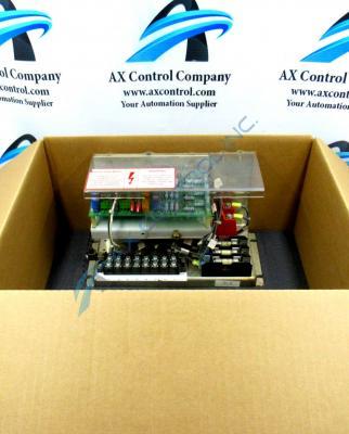
About the DS2020LPPA301A
The board is installed on standoffs on another component of the drive. The signal wires that connect to the board originate on the other component. To install the GE Line Protection Board DS2020LPPA301A on the standoffs, align the four holes on the board with the standoffs. You will notice that the board is designed to fit on the standoffs. Insert one screw into a standoff and use a screwdriver to tighten it. However, tighten it only enough so that it is snug. If you over tighten the screw, it might crack the board or bore the screw through the screw hole. These sort of instructions are crucially important to follow given the fact that General Electric took the time to include them in original Mark V Series instructional manual materials. While not a whole lot of other original instructional manual information is available for this Genera Electric product, its status alone as a General Electric product offering is helpful, as it will almost certainly possess the functional product number so key in identifying other hardware elements. The GE Line Protection Module DS2020LPPA301A features:
- 7 jumpers
- 2 terminal blocks
- test points
DS2020LPPA301A Module Number Insights
As explained immediately above, this DS2020LPPA301A Line Protection Board was manufactured by General Electric, and makes use of a functional DS2020LPPA301A product number. This product number is source of a high amount of product-specific hardware information, beginning with the DS2020 series tag detailing this DS2020LPPA301A GE Line Protection Board's special assembly version and original Salem, Virginia factory manufacture location. Some of the other important information glean-able from the DS2020LPPA301A product number of this Line Protection Board includes its:
- LPPA functional acronym
- 301A functional revision
- 301 style of PCB coating
This DS2020LPPA301A product's special iteration of Mark V Series assembly was more likely than not encouraged through its ownership of both a sturdy metal installation backplane on top of a plastic exterior cover designed to protect interior DS2020LPPA301A modular assembly components from an array of basic daily wear and tear damages.


