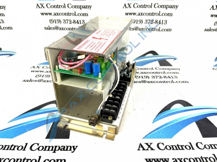
About the DS2020LPPA300A
As with any product developed specifically for General Electric's Mark V Turbine Control System Series, this DS2020LPPA300A PCB makes use of its own specific set of functionality-introducing hardware components and component specifications. For starters, the GE Line Protection Board DS2020LPPA300A features 7 jumpers and 2 terminal blocks with 3 terminals on each. The jumpers are identified as JP1 through JP7, and each jumper selects for specific applications as outlined in this DS2020LPPA300A product's originally-introduced instructional manuals. The GE Line Protection Board DS2020LPPA300A also contains test points. The board is installed on standoffs on another component of the Mark V Series automated drive. The signal wires that connect to the board originate on the other component. This DS2020LPPA300A Line Protection Board's status as a General Electric printed circuit board is somewhat perplexing, given its DS2020LPPA300A functional product number's assertion of a DS2020 modular assembly version. Some of the other information retrievable from this DS2020LPPA300A product's functional product number includes its:
- domestic location of original manufacture
- its LPPA functional acronym
- its special 300 style of PCB protection
- singular, A-rated functional product revision modifying said DS2020 special assembly
DS2020LPPA300A PCB Installation and Replacement
The terminal block in this DS2020LPPA300A printed circuit board's assembly can connect to a maximum of 6 signal cables. To avoid confusion when you replace the board, it is critical that you identify each signal cable and where it connects on the board. Each terminal block has an ID. One ID for a terminal block is TB1 and the other ID is TB2. Within each terminal block the individual terminals are numbered also from left to right. TB1 3 is the 3rd terminal on terminal block 1. For another example, TB2 2 is the 2nd terminal on terminal block 2. During installation of this DS2020LPPA300A PCB, normative activity involves:
- writing the ID for each signal wire on a slip of masking tape and applying it to the signal wire
- remove the signal wires from the terminals
- select the signal wire you want to remove and use a screwdriver to loosen the retention screw
- check that about 0.5 inch of wire has its insulation removed
- if less insulation is removed, use a knife to remove it
- if more is removed, cut the wire so that roughly 0.5 inch is removed
- pull out the signal wire from the terminal and move it to one side
It is crucial to follow this DS2020LPPA300A board's signal wire replacement instructions as this DS2020LPPA300A PCB is a static-sensitive model of circuit board that is generally fragile.


