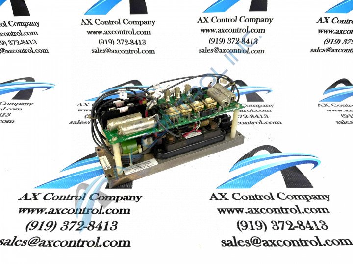
About the DS2020FECNRP025A
The board is installed on standoffs on another component of the drive. The signal wires that connect to the board originate on the component to which it is attached. The standoffs are attached with plastic screws and are also made of plastic. For this reason care must be taken when you attach the components together that you not over tighten the screws or use any excessive force. Use a flat-blade screwdriver and align the screws with the threaded portion of the standoffs. Connect the components together using all 4 standoffs and plastic screws. The GE Field Exciter Board DS2020FECNRP025A features:
- 7 jumpers and 2 terminal blocks with 3 terminals on each
- multiple prong-type connectors
DS2020FECNRP025A Product Number Breakdown
The DS2020FECNRP025A functional product number itself can be considered a strong primary source of DS2020FECNRP025A board-specific hardware component information, given its functional status as a General Electric number. For example, the DS2020FECNRP025A functional product number begins with the DS2020 series tag detailing both this DS2020FECNRP025A PCB's domestic original manufacture location as well as its special modular General Electric assembly. Some of the the other DS2020FECNRP025A board-specific details revealed in functional chunks of the DS2020FECNRP025A product number include this DS2020FECNRP025A PCB's:
- FECN functional product acronym
- RP Style of PCB coating
- A-rated functional product revision
DS2020FECNRP025A Device Connection and Interfacing
The terminal blocks in this DS2020FECNRP025A device's assembly connect to single copper signal wires. The signal wires connect the board to other boards and components in the drive. Some of the signal wires transmit signals to the GE Field Exciter Board DS2020FECNRP025A from other devices while other signal wires transmit signals from the board to other devices and components. The board receives signals from other boards and processing takes place to prepare the signals. Then, the signals are transmitted to another board for further processing. The terminals blocks each has an ID. The ID of one terminal block is TB1 and the other terminal block is TB2. Within each terminal the each terminal is identified by a number assigned in numerical sequence.
For example, on terminal block TB1, the terminals are identified as TB1 1, TB1 2, and TB1 3. Before making any final or ultimate purchase decision on this DS2020FECNRP025A product offering, it is crucial to understand the fact that this DS2020FECNRP025A PCB's A-rated functional product revision alters its originally-introduced basic performance specifications and dimensions.


