






About the DS200UPSAG1ADB
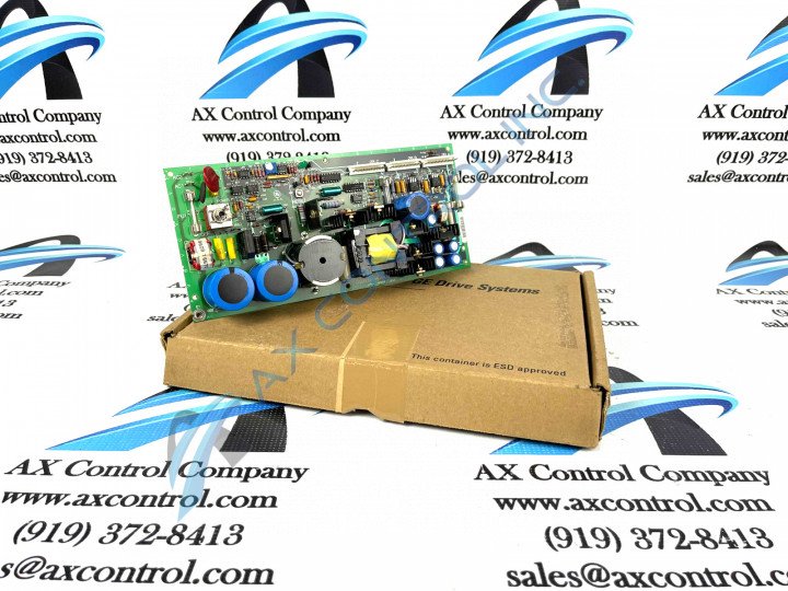
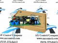
This DS200UPSAG1ADB Power Supply Board's intended Mark V Series functionality is accessed through its internal assembly's acceptance of several product-specialized hardware components and component specifications. The DS200UPSAG1ADB includes a toggle switch and a reset button. The reset is used for a hardware or hard reset. This is useful when the board experiences sudden faults or errors. The reset button can be used without removing power from the board, and interrupts instruction codes and other signals being received. If this doesn’t solve issues, the board also includes stab-on connectors that can be used as test points.
The board also has an inductor coil, resistor network arrays, resistors, and capacitors. Connectors can be made to the board through several vertical pin connectors located along its top board edge. The board is factory drilled at each corner and several more times along the board edges. It carries the GE logo and several other codes to help with location and wiring within the system. Other DS200UPSAG1ADB board components located on the DS200UPSAG1ADB include:
- a potentiometer
- a variable resistor
- several fuses
- a transformer
- over half a dozen heat sinks
- transistors
The DS200UPSAG1ADB Catalog Number
The initial DS200 series tag at the start of the DS200UPSAG1ADB functional catalog number details this DS200UPSAG1ADB Power Supply Board's normal style of Mark V Series assembly as well as its domestic original manufacture location. Some of the other DS200UPSAG1ADB Board-specific details revealed through an analysis of the DS200UPSAG1ADB number includes this DS200UPSAG1ADB PCB's:
- UPSA functional product abbreviation
- Normal style of PCB surface coating
- Group one Mark V Series product grouping
- A-rated primary functional revision
- D-rated secondary functional revision
- B-rated artwork configuration revision