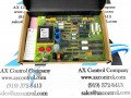
About the DS200UPLAG1A
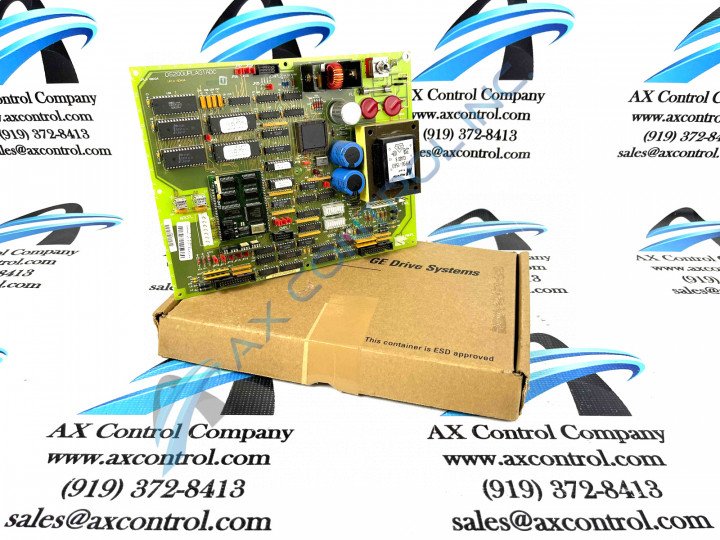
As with any Mark V Series printed circuit board product offering, this DS200UPLAG1A PCB's assembly is chock full of functionality-inducing hardware components and component specifications. The GE LAN Power Supply Circuit Board DS200UPLAG1A contains two 26-pin connectors, 1 fuse, and 1 toggle switch. The board also has 1 reset button and 1 8-pin connector. In addition to these specific DS200UPLAG1A board hardware options, a number of Mark V Series-standardized hardware components geared towards voltage limitation are available to this product's assembly, including various rectifiers, capacitors, diodes, and integrated circuits.
Any hardware component made available to the assembly of this DS200UPLAG1A LAN Power Supply Card should be at least somewhat protected by the normal style of PCB coating that has been applied to its base circuit board; this normal PCB coating exists as a thick layer of rudimentary daily wear and tear protection and insulation that envelops and protects individual DS200UPLAG1A board hardware elements on a functional priority basis. This DS200UPLAG1A PCB's normal PCB coating style was discovered upon an analysis of the DS200UPLAG1A functional product number itself, which contains other handy hardware details including this DS200UPLAG1A product's:
- Normal Mark V Series assembly
- Domestic original manufacture location
- UPLA functional product abbreviation
- Group one Mark V Series product grouping
- A-rated primary functional revision
DS200UPLAG1A Installation
To install the GE LAN Power Supply Circuit Board DS200UPLAG1A, you must:
- inspect the old board and note the cables attached to the old DS200UPLAG1A board, as well as the jumper settings and switch settings
- while the cables are still attached to the old board, note all the cables attached to it and identify by connector number where they connect on the board
- tag the cable with that information before you disconnect the cables
- use a screwdriver to remove the four screws and remove the board from the drive
- hold the board by the edges and place it on a flat surface that is free of dust and debris
- remove the replacement board from the static protective bag and be sure to only hold the board by the edges
- with one hand, smooth out the static protective bag and place the replacement board on it
- first, inspect the old board and note the positions of all the jumpers
- move the jumpers on the replacement board to match the positions
- use two fingers to lift each jumper from the pins and insert the jumper over the pins for the new position
- note the positions of the switches on the old board and move the switches on the replacement board to match them