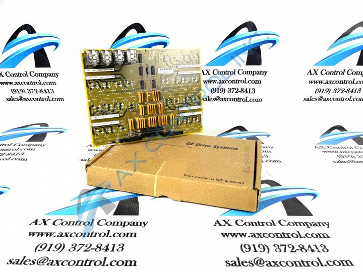
About the DS200TCRAG2A
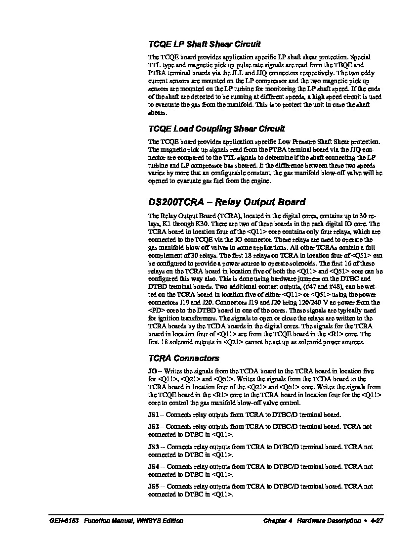
This model was designed by General Electric as a Relay Output terminal board that operates in the Q11 and Q51 cores; there are two TCRA models within each I/O core. When the model has been mounted within the cores, it will be connected to the TCQE model through the JO connectors on the TCRA board. When the model is in the Q11 core, there are only four relays; the four relays are primarily used to operate the gas manifold blow-off valves in some applications. When the DS200TCRAG2A model has been mounted in the Q51 core, the first eighteen relays on the model will be configured to provide a power source to operate the solenoid outputs. To configure the relays, it will be done through the hardware jumpers on the DTBD and DTBC terminal boards connected alongside the TCRA board. While the TCRA model has a number of hardware configurations that are used to configure the model to the user's specifications, the model does not contain any software configurations. It should be noted that while this DS200TCRAG2A Relay Output Terminal Board is offered alongside customization strategies encouraged by customizable hardware, the customizable hardware in question is not present in the assembly of this DS200TCRAG2A Relay Output Board itself; existing in the configurations of the related Mark V Series DTBC and DTBD terminal board products. There are several connectors available on the DS200TCRAG2A model; some of them are as follows:
- The JS5 Connector
- The JS6 Connector
- The JS7 Connector
- The JS8 Connector
All of these connectors are used to connect relay outputs from this model to the DTBC or DTBD boards. When the TCRA model is used in the Q11 core, it will not be connected to the DTBC models. There are also the JOR/S/T connectors, but typically these connectors are not used by the TCRA model. All of the other connectors and their functions are listed in the fourth chapter of the GEH-6153 Instruction Guide, embedded above in the manuals tab.
TCRA Relay Output Terminal Board Part Number
The DS200TCRAG2A functional product number itself reveals a litany of other DS200TCRAG2A board-specific hardware components and component specifications, as it was developed to serve this purpose by General Electric. Some of the information revealed through use of this DS200TCRAG2A functional product number includes this DS200TCRAG2A board's:
- Domestic location of original manufacture
- Normal Mark V Series assembly type
- TCRA functional product acronym
- Normal style of PCB protective coating
- Group One Mark V Series grouping
- A-rated functional product revision


