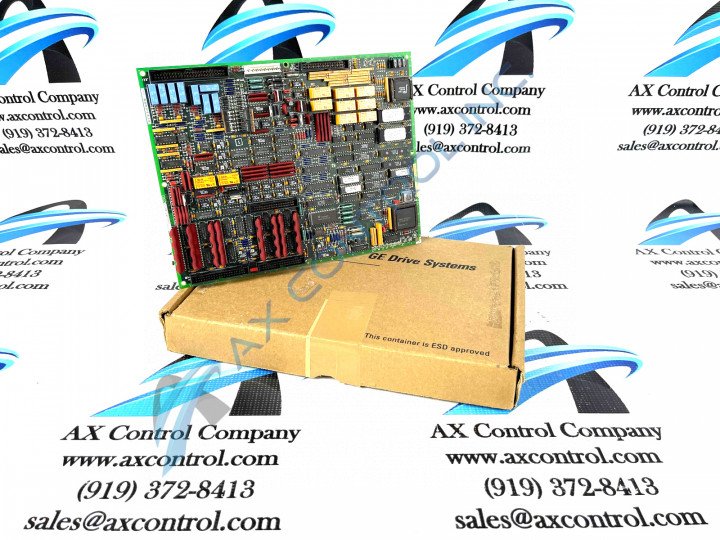
About the DS200TCQFG1ACC
This DS200TCQFG1ACC Circuit Board from General Electric's Mark V Series is actually better-definable as a TC2000 Analog I/O Extension Card; its original functional description that appears in General Electric instructional manual materials. This Mark V Series product offering is a modified version of a preexisting General Electric printed circuit board; changing the assembly of the DS200TCQFG1ACC TC2000 Analog I/O Extension Card through its insertion of three differently-rated significant product revisions.
While not a whole lot of original instructional manual materials surrounding this DS200TCQFG1ACC Analog I/O Extension Card are available online, its DS200TCQFG1ACC functional product number and a thorough visual inspection are decent informational sources.
Hardware Tips and Specifications
The GE TC2000 Analog I/O Extender Board DS200TCQFG1ACC is populated with:
- 7 jumpers
- 2 50-pin connectors
- 1 34-pin connector
- 1 9-pin connector
The ID assigned to the 34-pin connector is JA. The IDs assigned to the 50-pin connectors are JUU and JB. Six LEDs are located on the GE TC2000 Analog I/O Extender Board DS200TCQFG1ACC. The LEDs can be viewed when the board is installed in the drive and the LEDs are green in color when lit. Each LED is associated with a circuit or function on the board. When the drive is receiving power and the board is processing as normal, the LEDs are lit and when activity is taking place on the circuit associated with the LED, the LEDs flash. In this way, the operator can easily monitor the function and health of the board while the drive is operation. If the LEDs are not lit, you can check several factors to begin to narrow down the cause, as outlined in original General Electric instructional materials. First verify that the drive is operating and receiving power. If the drive is not receiving power, the board will not function. If the drive is receiving power, shut down the drive and disconnect and connect all cables to the board to make sure they are fully seated in the connectors. You should see no space between the connectors when the cables are properly connected. You can use the diagnostics tools on the drive to check for error codes or indications of other problems.
This DS200TCQFG1ACC TC2000 Analog I/O Extension card is a normal-assembly Mark V Series product with a full three-fold revision history. Both of these facts are retrievable from the DS200TCQFG1ACC functional product number, which features additional details such as this DS200TCQFG1ACC board's:
- TCQF functional acronym
- domestic manufacture location
- normal style of PCB coating
- group one Mark V Series grouping


