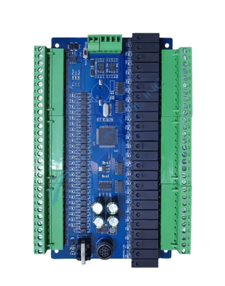
About the DS200TCQEG1A
The LM6000 I/O Processor Board DS200TCQEG1A is populated with 8 jumpers and 4 34-pin connectors. It also features one programmable logic device and multiple EPROMs. The IDs assigned to the 34-pin connectors are JQQ, 3PL, and JLL. The LM6000 I/O Processor Board DS200TCQEG1A also is populated with one LED that is mounted horizontally on the board. The board is 8.5 inches in width and 11 inches in height and it contains four holes for securing the board to the board rack in the interior of the drive. The board also is populated with heat sinks to cool some components on the board that tend to get hot during operation. The heat sinks protrude from the surface of the board and might cause damage to other boards or components. There is a danger that the installer might scrap against other components accidentally with the heat sink or cause components to break off the board.
DS200TCQEG1A Device Connectors
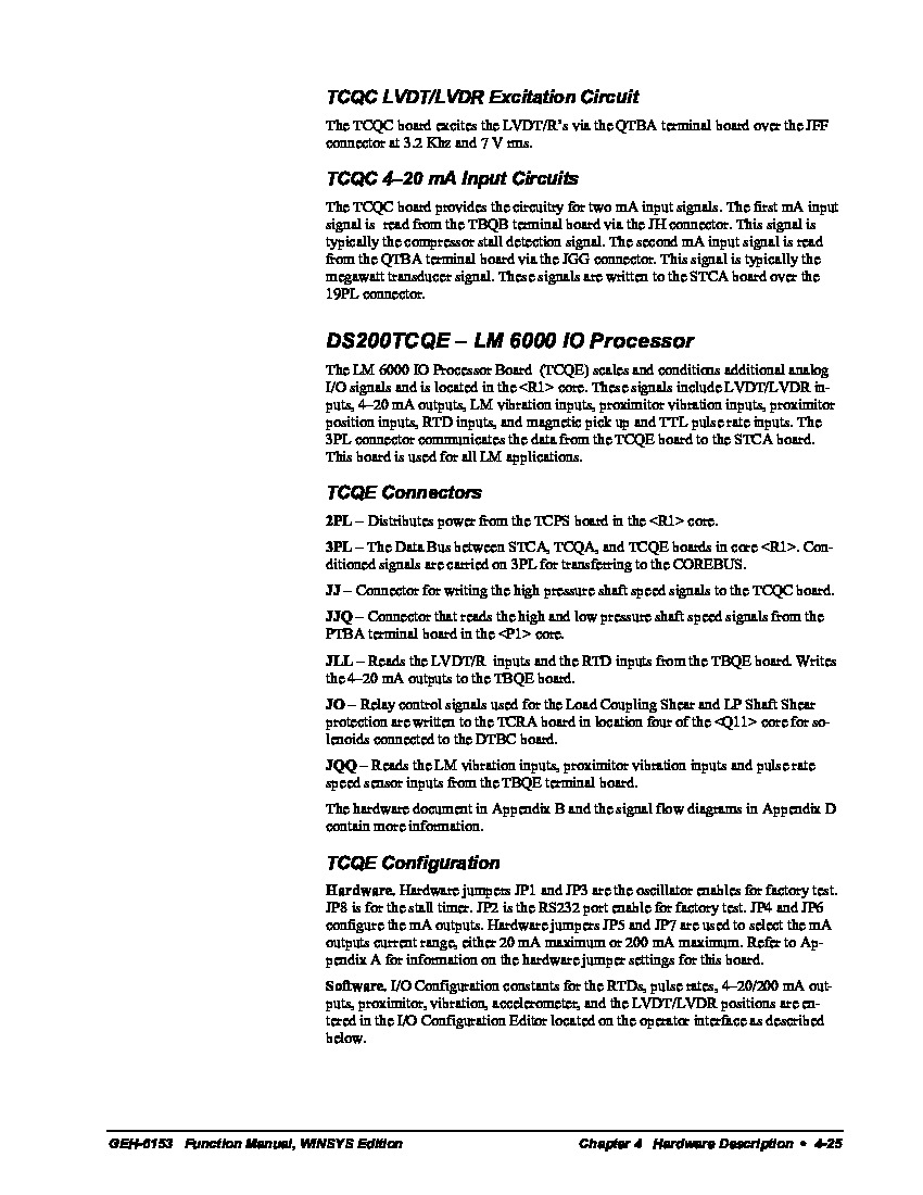
Several specific styles of Mark V Series connectors have been included in the assembly of this DS200TCQEG1A product offering. Each one of these connectors is accompanied by their own factory-printed nomenclatures, as referenced above. With this being true, it is fortunate that this DS200TCQEG1A PCB is well-referenced in originally-printed and internet-available instructional manual materials; this mean that each of its connectors has been described in detail. Some of this DS200TCQEG1A Board's connectors include:
- The 2PL TCPS Board Power Distribution Connector
- The 3PL STCA, TCQA, and TCQE Boards Conditioned Signals Connector
- The JJ TCQC Board Shaft Speed Signals Connector
- The JJQ PTBA Board Shaft Speed Signals Connector
- The JLL TBQE Board LVDT/R Input Signals Connector
- The JO TCRA Board Relay Control Signals Connector
- The JQQ TBQE Board Input Signals Connector
DS200TCQEG1A Board Heat Sink Installation
Each of the connectors listed in the assembly of this DS200TCQEG1A product offering above have been named through a combination of their individual factory-printed nomenclature labels, their Mark V Series compatible products and interfacing potentials, and finally their specific intended application. There is also the possibility that the heatsink might be broken off when the board is lifted into the drive or removed from the drive. To avoid that:
- have a good view of the board when you move the board around the cabinet
- best practice to work slowly
- note where the board is installed and also note where the cables are connected to it
- install it in the same location
- it cannot be sandwiched together closely with other boards
- heat sinks require that air is able to more freely around the board


