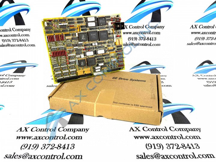
About the DS200TCQBG1BBA
The DS200TCQBG1BBA functions as an RST Overflow board within the General Electric company’s Mark V Turbine Control System. The Mark V Series that this DS200TCQBG1BBA printed circuit board belongs to has specific applications in the management and control systems of popular and compatible gas, steam, or wind turbine automated drive assemblies.
Hardware Tips and Specifications
The DS200TCQBG1BBA is a large, rectangular board that is heavily populated on its top surface. The board is drilled at each of its corners, allowing for mounting within the drive. It is marked with the General Electric logo and also carries the individual board ID number that differentiates it from other PCBs. For starters, this DS200TCQBG1BBA printed circuit board product offering is not the original RST Overflow Board manufactured for placement in the Mark V Turbine Control System Series. The original product of this specific functional role developed for the Mark V Series is the DS200TCQBG1 parent RST Overflow Board not making use of this DS200TCQBG1BBA PCB's three-fold revision history including two B-rated functional product revisions and its singular A-rated artwork configuration revision.
The DS200TCQBG1BBA functional product number itself can be identified as a strong source of DS200TCQBG1BBA hardware component and component specification information, coding for various DS200TCQBG1BBA Board hardware components and component specifications in a series of functional naming chunks. For example, the DS200TCQBG1BBA functional product number begins with the dual-functional DS200 series tag delegating this DS200TCQBG1BBA PCB's normal Mark V Series assembly version as well as its domestic original manufacture location. Some of the other relevant hardware details revealed in the DS200TCQBG1BBA functional product number include:
- its TCQB functional product abbreviation
- its normal PCB coating style
- its group one Mark V Series product grouping
- its full, three-fold revision history
The DS200TCQBG1BBA includes many different components. This includes:
- vertical pin and plug connectors
- two relays
- a green LED indicator
- multiple resistor network arrays
- transistors
- integrated circuits including FPGAs
- jumper switches
The board has more than a dozen jumpers, including five located in a single line about one-quarter of the way in from the left-hand side of the board. Most components are marked with reference designations to allow for easy identification but refer to General Electric manuals and user guides for additional information. The board also has two heat sinks mounted near one corner. Heat sinks allow components to dissipate heat more quickly than they otherwise would, allowing the components and the board to maintain a proper operating temperature.


