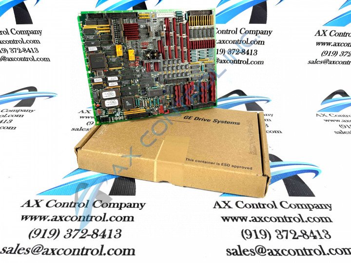
About the DS200TCQAG1B
This DS200TCQAG1B printed circuit board is a product offering designed and produced by General Electric. This DS200TCQAG1B printed circuit board or PCB for short can be more succinctly tracked down to General Electric's Mark V Series, a product series of gas, steam, and wind turbine control systems and control system component products that features the same Speedtronic technology seen in General Electric printed circuit board since the rollout of the earlier Mark I Series in the late 1960s.
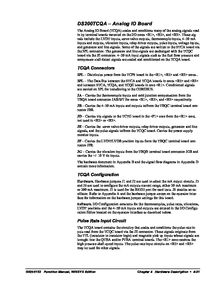
This DS200TCQAG1B PCB is better-definable as an Analog I/O Board; the original functional product description that it received in General Electric and Mark V Turbine Control System Series printed instructional manual documentation. While this DS200TCQAG1B product offering is indeed definable as an Analog I/O Board, it is not the first General Electric product of its exact intended functionality to be developed for the Mark V; that would be the DS200TCQAG1 Analog I/O Board missing this DS200TCQAG1B product's functional product revision.
Hardware Tips and Specifications
As with any printed circuit board product offering offered alongside the Mark V Turbine Control System Series, this DS200TCQAG1B Analog I/O Board makes use of a specialized set of hardware component inclusions and specifications. The GE RST Analog I/O Board DS200TCQAG1B contains four 34-pin connectors, two 40-pin connector, and six jumpers. The board also has 6 LEDs. The GE RST Analog I/O Board DS200TCQAG1B is designed to be installed in the board cabinet in the drive. The board cabinet has racks for the installation of the board, and the DS200TCQAG1B board itself features screw holes that align with the rack and enable you to use screws to secure the boards. In observance of potentially-present damaging surface voltages, these factory-drilled holes have been ringed with an insulated material.
The DS200TCQAG1B functional product number is a strong source of identification information for this DS200TCQAG1B PCB, given a relative unavailability of its original instructional manual. Some of the details embedded in this factory-formulated product number include:
- A normal style of Mark V Series assembly
- A domestic location of original manufacture
- The TCQA functional product abbreviation
- A normal style of PCB protective coating
- A group one Mark V Series grouping
- A singular, B-rated functional product revision
While identifying some of the crucial hardware components in this DS200TCQAG1B PCB's assembly is certainly crucial, so too is understanding normative installation processes for this DS200TCQAG1B PCB, as described by General Electric. When you remove the old board, retain the screws and washers that secure the old board and keep them in a safe place for later use when you secure the replacement board. If any of the screws or washers fall into the drive interior, stop what you are doing, locate them, and remove them from the drive. If you start the drive with loose debris it might cause injury due to the high-voltage electric current or the moving parts might became jammed or damaged. It is best practice to use two hands when you remove or install the screws. Use one hand to turn the screwdriver and one hand to hold the screws and washers.


