About the DS200TCQAG1A
This DS200TCQAG1A printed circuit board or PCB for short is better-classifiable as an Analog IO Board, the original functional product description that it is referred to as in Mark V Turbine Control System Series instructional manual materials. The Mark V Series that this DS200TCQAG1A PCB belongs to, as indicated in part by its name, has specific applications in the control and management systems of wind, gas, and steam turbine automated drive assemblies.
This DS200TCQAG1A Analog IO Board is not the original product with its specific functionality to exist as a member of the Mark V Series; that would be the DS200TCQAG1 parent Analog IO Board missing this DS200TCQAG1A product offering's A-rated functional product revision.
Hardware Tips and Specifications
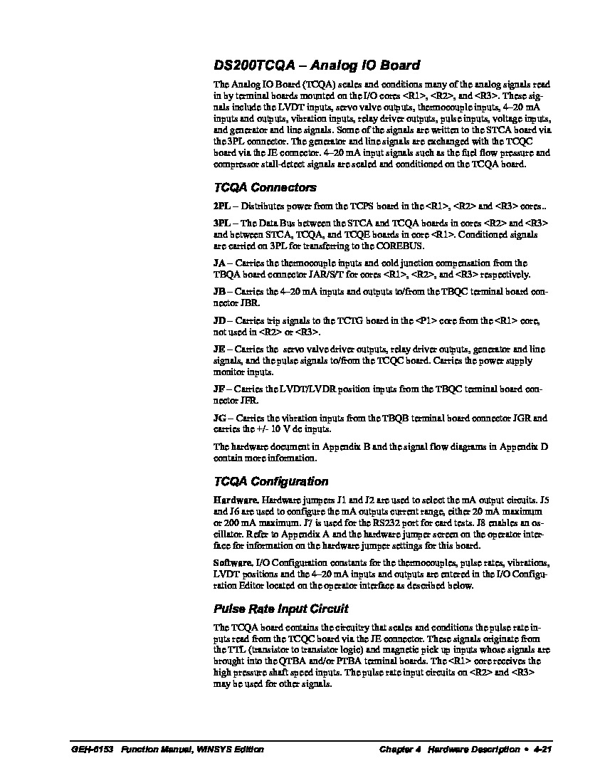
The DS200TCQAG1A model is one of the many boards in the Mark V series produced by General Electric, and utilizes its own series of hardware components and component specifications to achieve its true functional status. This model is labeled as an Analog I/O board and is most commonly used to scale and condition other Mark V models located in the Mark V cabinet in three I/O cores labeled as:
The signals that the DS200TCQAG1A model collects are thermocouple inputs, servo valve outputs, vibration inputs, generator/line signals, relay drive outputs, voltage inputs, pulse inputs, 4-20 mA inputs/outputs, and LVDT inputs. The generator and line signals will be exchanged with the TCQC board through the JE connector on the DS200TCQAG1A model. The 4-20 mA inputs signals, such as compressor stall-detect signals and fuel flow pressure, will be conditioned and scaled on the TCQA board. While this DS200TCQAG1A product may benefit from its possession of an atypical selection of internet-available instructional manual materials, that doesn't mean that it doesn't also benefit from a DS200TCQAG1A functional product number displaying a number of other relevant DS200TCQAG1A Board details, including this DS200TCQAG1A PCB's:
- Domestic original location of GE manufacture
- TCQA unique product abbreviation
- Group one Mark Series product grouping
- Normal PCB coating style
- A-rated functional product revision
There are eight connectors available on the TCQA board; these connectors are labeled JG, JF, JE, JD, JB, JA, 2PL, and 3PL. Each of the connectors has its own functions. One example connection function is LVDR/LVDT position inputs being carried from the TBQC terminal boards JFR connector through the JF connector on the DS200TCQAG1A model. For the remaining functions of the other TCQA connectors, refer to the GEH-6153 data sheet attached above under the manuals tab. One of the circuits of the DS200TCQAG1A model is the thermocouple circuit; these thermocouples are connected to the TBQA terminal board. The thermocouple circuits are also located on the TVQA terminal board to provide thermocouple cold junction references; the cold junction references can be used by the TCQA board to calculate the cold junction compensation within the Mark V system.
All of the hardware components and component specifications made useful to this DS200TCQAG1A Analog I/O Board should receive at least some level of protection from the normal style of PCB protective coating that has been applied to the base circuit board of this DS200TCQAG1A PCB. This normal style of PCB coating is a thick, rudimentary layer of PCB daily wear and tear protection and insulation that envelops and protects individual hardware elements in the DS200TCQAG1A PCB's assembly on a functional priority basis. Before making an ultimate purchase decision on this DS200TCQAG1A printed circuit board, it is important to realize that the A-rated functional product revision present in its assembly alters it from its original factory-introduced performance specifications and dimensions.


