About the DS200TCPDG1BDC
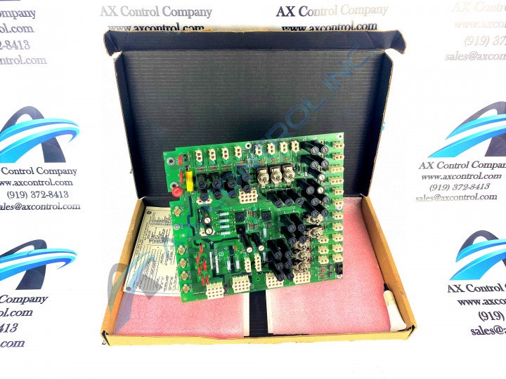
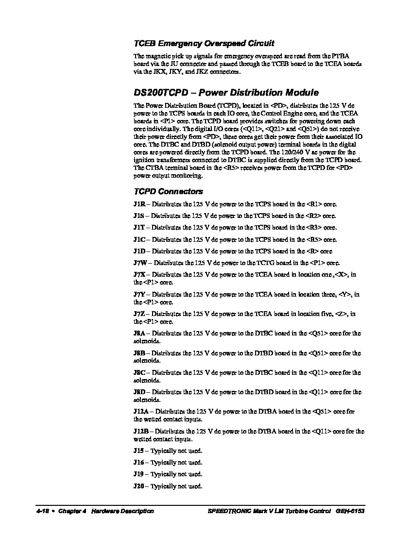
Model number DS200TCPDG1BDC is a power distribution board mounted in the Mark V system manufactured by General Electric. This model is located in the <PD> core and will distribute a power supply of 125 V DC to the Control Engine core, the power supply (TCPS) boards in each I/O core, and the three emergency overspeed (TCEA) boards in the protective <P1> cores. When the TCPD model has provided the power supply to the aforementioned models, it can provide switches to power down the cores individually. This DS200TCPDG1BDC Power Distribution Card's Mark V Series is one of the more recently-developed Mark Series from General Electric, designed using the same Speedtronic technology utilized beginning in the late 1960's with the Mark I.
This DS200TCPDG1BDC printed circuit board or PCB for short is not the original Power Distribution Card manufactured for the Mark V, however, as it modified the original DS200TCPDG1 parent Power Distribution Card through the addition of a B-rated functional product revision and two others.
The Mark V Series that this edited DS200TCPDG1BDC PCB belongs to has applications specifically in wind, gas, and steam turbine management or control systems.
Hardware Tips and Specifications
As mentioned above, this DS200TCPDG1BDC Power Distribution Card plays an important and specific role within the greater Mark V Series of products, which means that it will utilizes its own specific series of hardware components and component specifications. There are several cores within the Mark V system that the DS200TCPDG1BDC board will interact with, but some of the I/O cores cannot be interacted with; the cores that the TCPD model will not interact with, which includes the <Q11>, <Q21>, and <Q51> cores, these cores will receive their power from other I/O cores.
There are two solenoid output power boards, the Contact Output Termination (DTBC) and Contact Output Expansion Termination (DTBD) modules located in the digital cores, that will collect power directly from the DS200TCPDG1BDC model. The TCPD board is also used in providing power in the amount of 120/240 V ac to the ignition transformers connected to the DTBC boards. Several different types of switches are available to the external assembly of this DS200TCPDG1BDC Power Distribution Board, for intuitive power distribution selection. These various switches include:
- The SW1 R1 Core Power Toggle
- The SW2 R2 Core Power Toggle
- The SW3 R3 Core Power Toggle
- The SW4 R5 Core Power Toggle
- The SW5 R Core Power Toggle
- The SW6 P1 Core X Power Toggle
- The SW7 P1 Core Y Power Toggle
- The SW8 P1 Core Z Power Toggle
All of these above listed switches in the assembly of this DS200TCPDG1BDC Power Distribution Card have been named through a combination of their respective factory-printed nomenclature label and their interfacing potential with other boards and cores within the Mark V Turbine Control System Series. The switches in the assembly of this DS200TCPDG1BDC Power Distribution Card should be at least somewhat-protected by use of the normal style of thick, rudimentary printed circuit board coating that has been applied to the base circuit board of this DS200TCPDG1BDC printed circuit board.
Before making a final purchase decision on this DS200TCPDG1BDC PCB, it is crucial to be cognizant of the fact that this DS200TCPDG1BDC product offering's original performance specifications and dimensions have no doubt been altered through insertion of this product's three total significant product revisions. For more information regarding the connectors and connections on the DS200TCPDG1BDC model as well as how the model is used with the boards in the Mark V system, refer to the GEH-6153 manual.


