About the DS200TCEBG1BAA
This DS200TCEBG1BAA printed circuit board product offering was originally designed and produced by General Electric, for placement in their Mark V Turbine Control System Series.
The DS200TCEBG1BAA Mark V Series product's greater Mark V Series does still possess specific applications in newer-developed applications including the management and control systems of compatible wind, steam, and gas turbine automated drive assemblies. This DS200TCEBG1BAA Board's greater Mark V Series is additionally definable as a desirable GE product series as it exists as one of the lastly-developed GE Mark product series to utilize the Speedtronic control system technology across a range of offerings.
This DS200TCEBG1BAA PCB was developed for the specific functional role of a Protective Termination Expander Board, although it is not the originally-developed product of this specific Mark V Series functionality. The original Protective Termination Expander Board developed for the Mark V Series is the DS200TCEBG1 parent printed circuit board missing this DS200TCEBG1BAA PCB's three-fold revision history.
Hardware Tips and Specifications
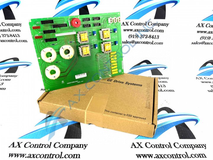
As with any Mark V Series product made available to our new and extended reconditioned inventory here, this DS200TCEBG1BAA PCB's specific functional role is embraced with its normal Mark V Series assembly's attachment of a specific series of functionality-inducing hardware components and component specifications. The GE Protective Termination Expander Board DS200TCEBG1BAA features:
- 3 bayonet connectors
- 4 signal transformers
- 1 26-pin connector
- 4 10-pin connectors
- 3 20-pin connectors
The signal transformers that populate the board are used to increase the compatibility of the signals between two devices. The board is also populated with 3 20-pin connectors. The 20-pin connectors are labeled JKZ JKX, and JKY. The 20-pin connectors are connected to signal carrying ribbon cables. The signal are transmitted to the DS200TCEBG1BAA board from other boards in the interior of the drive. Other signals are transmitted to other boards in the drive.
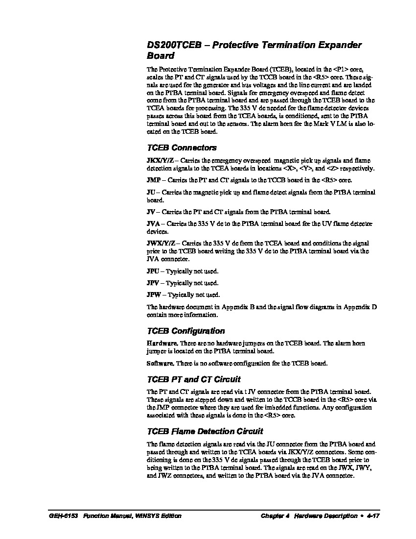
Luckily enough for the purposes of this DS200TCEBG1BAA personalized product page here, this DS200TCEBG1BAA PCB's various connectors have been listed in the DS200TCEBG1BAA instructional manual embedded in the manuals tab above for your convenience. As referenced before, each of this DS200TCEBG1BAA PCB's connectors will be accompanied by their own factory-printed nomenclature label. Some of the various connectors important to the assembly of this DS200TCEBG1BAA Mark V Series product include:
- The JKX/Y/Z TCEA Board Various Signals Connector
- The JMP TCCB Board PT and CT Signals Connector
- The JU PTBA Board Magnetic Pickup and Flame Detection Signals Connector
- The JV PTBA Board PT and CT Signals Connector
- The JVA PTBA Board Flame Detection Signals Connector
- The JWX/Y/Z Board TCEA Board Conditioned Signals Connector
- The JPU Connector
- The JPV Connector
- The JPW Connector
Each of the previously-listed connectors in the normal assembly of this DS200TCEBG1BAA Mark V Series product offering have been named through a unique connection of their individual factory-printed nomenclature labels, their Mark V Series compatible products, and finally the styles of signals that they were designed to transmit to the DS200TCEBG1BAA Board and its greater Mark V Series automated drive assembly. This DS200TCEBG1BAA PCB's DS200TCEBG1BAA functional product number can be considered an additional fine source of DS200TCEBG1BAA Board hardware component and component specification information, revealing details including this DS200TCEBG1BAA Board's:
- normal Mark V Series assembly version
- its normal PCB coating style
- its group one Mark V Series product grouping
- its full, three-fold revision history
Ribbon cables are made up of fragile fine wires so they require some special consideration when you disconnect them or connect them. When you plan to disconnect the 20-pin ribbon cables, it is important that you first attach a tag or label to them that IDs the connector that it is attached to. Doing that will reduce the opportunity to connect the ribbon cable into the wrong connector and thereby force the installer to reconnect the cables and delay when the drive is back online. Once the ribbon cables are labelled, hold the ribbon cable connector at the end of the cable and gently pull it out of the connector. If necessary, use your other hand to hold the board and keep it from moving. Move the ribbon cable aside so you can access the board. However, do not disturb the cable routing. The ribbon cable is routed to reduce interference that can be caused by running the ribbon cable in parallel with power cables.


