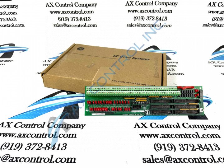
About the DS200TBQCG1ABB
This DS200TBQCG1ABB General Electric printed circuit board product offering was originally offered as a member of the Mark V Turbine Control System Series which has specific applications in the control and management systems of wind, gas, and steam turbine assemblies. The Mark V Turbine Control System Series is one of the more recently-developed General Electric product series incorporating their signature patented Speedtronic technology into its assembly.
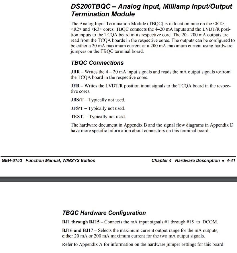
This DS200TBQCG1ABB printed circuit board or PCB for short is better-definable as an Analog Input Milliamp I/O Termination Module, the official functional product description that it is referred to as in original Mark V Series instructional manual materials.
While an Analog Milliamp I/O Termination Module in its own right, this DS200TBQCG1ABB PCB is not the original product of its intended functionality to exists within the Mark V; that would be the DS200TBQCG1ABB Analog Milliamp I/O Termination Module missing this DS200TBQCG1ABB board's three crucial product revisions.
Hardware Tips and Specifications
As with any Mark V Series product offering with a normal Mark V assembly style, this DS200TBQCG1ABB printed circuit board necessitates a particular series of hardware components and component specifications to gain its intended series functionality. The GE RST Analog Termination Board DS200TBQCG1ABB features 2 terminal blocks, with each block containing 83 terminals for signal wires. The GE RST Analog Termination Board DS200TBQCG1ABB also contains 15 jumpers, 3 40-pin connectors, and 3 34-pin connectors. Luckily enough for our purposes, the exact applications of these various connectors are described in detail in original Mark V Series instructional manual materials. Some of these different connector types include:
- The JBR TCQA Board Input/Output Signals Connector
- The JFR TCQA Board LVDT/R Position Input Signals Connector
- The JBS/T Connector
- The JFS/T Connector
- The TEST Connector
All of these listed connectors in the assembly of this DS200TBQCG1ABB Analog Input Milliamp I/O Termination Module have been named through a combination of their original factory-printed designator labels, their compatibility with other Mark V Series printed circuit boards, and their specific DS200TBQCG1ABB board and Mark V Series automated drive assembly applications, except fot the JBS/T, JFS/T, and TEST connectors. These three relevant connectors in the assembly of this DS200TBQCG1ABB Module typically go unused during normal function, so they have not been functionally named. Various configurations for this DS200TBQCG1ABB product offering's manually-moveable hardware jumpers are available in this DS200TBQCG1ABB PCB's original instructional manual attached above in the manuals tab.
The DS200TBQCG1ABB board is 11.25 inches in length and 3 inches in height and it is engineered for installation in the rack cabinet, and has one hole for attaching the board in each corner. Each of these corner-placed factory-drilled installation holes has been insulated to avoid static electricity damage to the DS200TBQCG1ABB base circuit board. When you install the DS200TBQCG1ABB board, it aligns with the matching holes in the rack, and you can attach the board with screws that you obtain from removing the defective board. Only a qualified servicer will be able to replace the DS200TBQCG1ABB board because of the danger from the high voltage present in the drive, even when power is removed from the drive, capacitors and other components store voltage. If the voltage is still present in the drive, serious injury can occur when attempting installation. The DS200TBQCG1ABB PCB's capacitors lose the voltage stored in them after 30 seconds so best practice is to wait 30 seconds after power is removed before you touch any components. Before making a final purchase decision on this DS200TBQCG1ABB Analog Input Milliamp I/O Termination Module, it is important to be aware of the fact that this General Electric printed circuit board or modular assembly has been revised from its original performance specifications and dimensions three times.


