About the DS200SPCBG1ADC
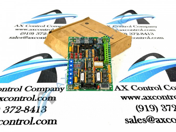
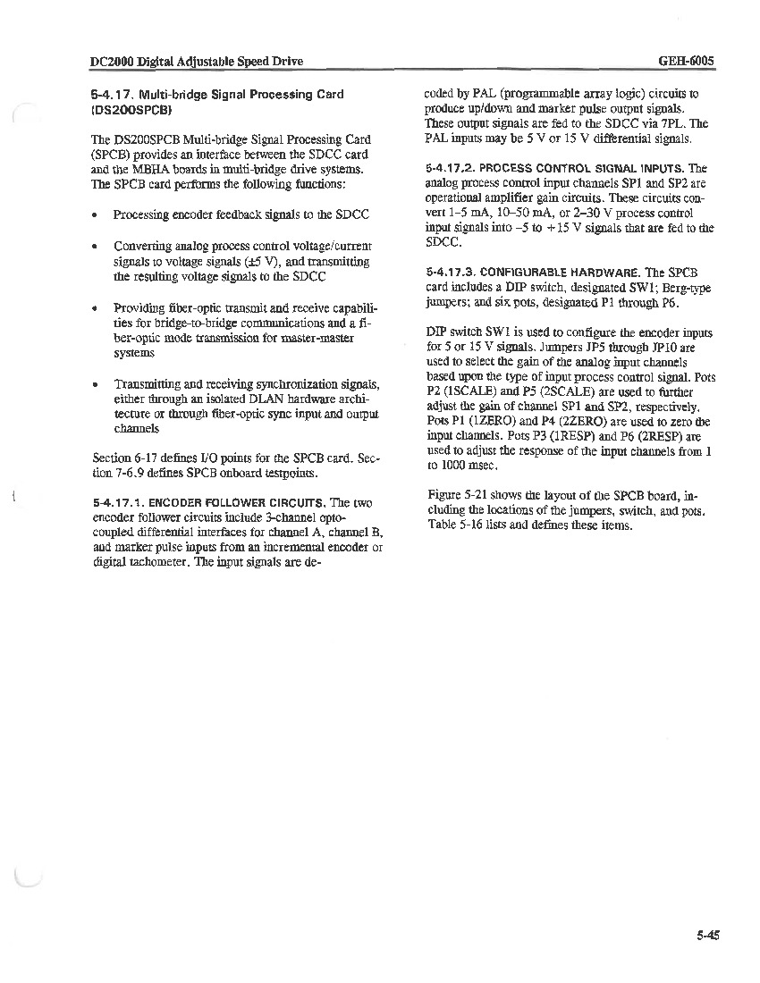
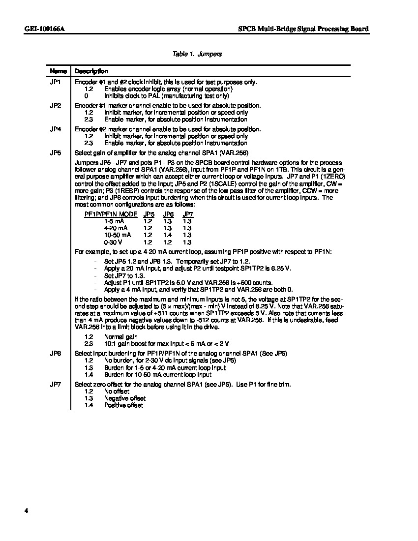
The GE Multi-Bridge Signal Processing Board DS200SPCBG1ADC is an interface between the drive control board and the multi-bridge hub communications board. Two functions of the board are to convert the analog process control signals to digital signals and transmit the results to the drive control board. Another function is to transmit and receive synchronization signals through the fiber optic ports. The fiber optic ports are used to transmit and receive bridge-to-bridge or master-to-master communications. Jumpers are on the board that you can use to configure the fiber optic network.
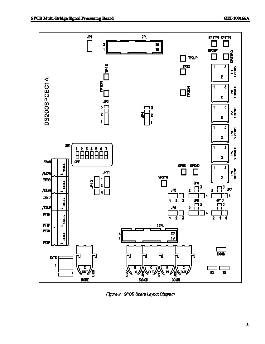
There are two sets of fiber optic ports on the board for bridge-to-bridge communications. One set is for the communications and the other set is used for synchronization of the signal. In each pair one port is blue and the other port is gray. The blue port is for the receiving cable and the gray is for the transmitting cable. A fifth fiber optic port is also on the board. It is dedicated to the master-to-master communications functionality. You will find that the fiber optic network is easy to route in a manufacturing environment. The manufacturing environment is often crowded with:
- 3-phase high-voltage cables
- signal cables
- network communications cables
- grounding cable
- multiple other cables
Specific Possible DS200SPCBG1ADC Connections
Interference often occurs between cables when the signals from one electrical cable creates noise that disturbs another signal. Fiber optic cables cannot be interfered with through electrical signals. This means that fiber optic cables can be routed next to high-voltage cables without picking up interference. Many of the specific connectors in this DS200SPCBG1ADC product offering's assembly have been listed in the DS200SPCBG1ADC instructional manual attached in our convenient manuals tab above. For example, this DS200SPCBG1ADC printed circuit board has two total connectors meant for the synchronization of drive output; these connectors are:
- the SYNC Pin No. 1 non-inverting drive synchronization signal connector
- the /SYNC Pin No. 2 inverting drive synchronization signal connector
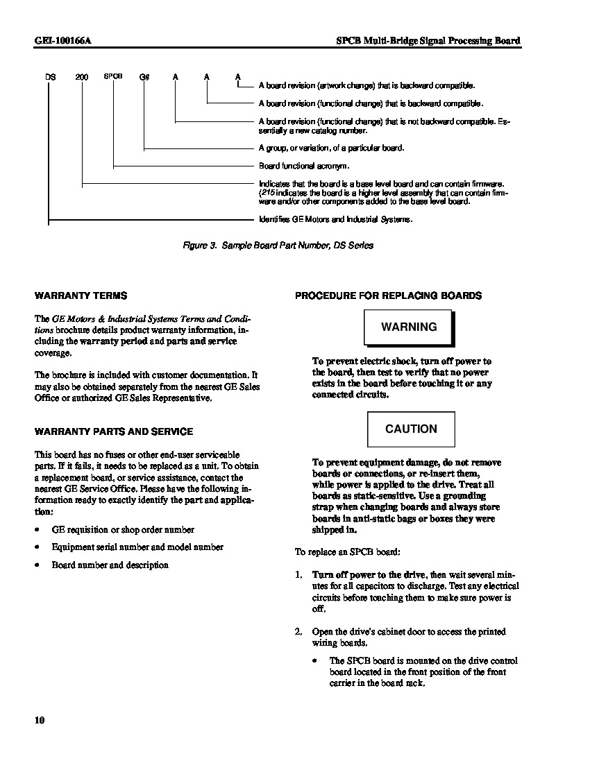
Before making any final purchase decision on this DS200SPCBG1ADC PCB, it is crucial to realize that it has been edited from its originally-introduced performance specifications and dimensions through use of two functional product revisions and an artwork configuration revision rated at grades of A, D, and C, respectively.


