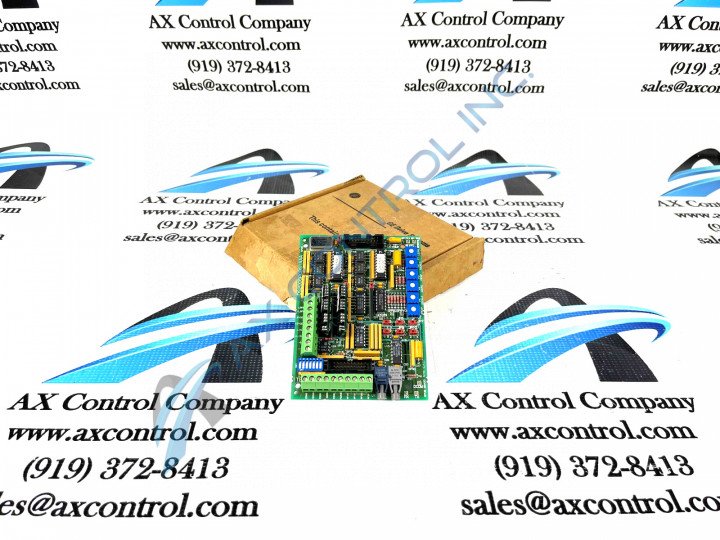
About the DS200SPCBG1AAA
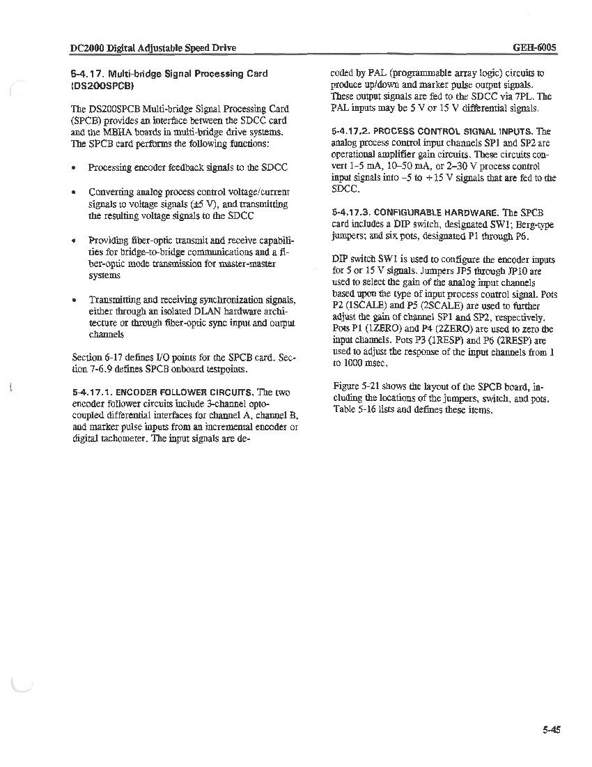
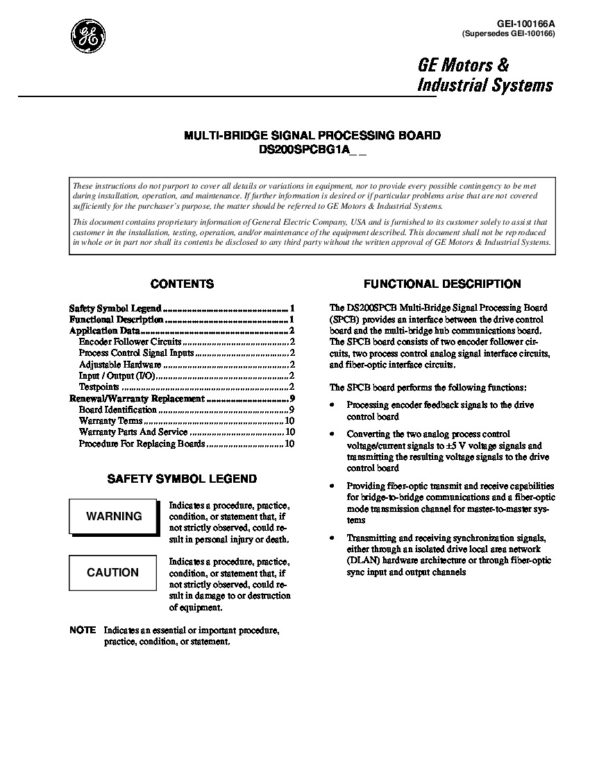
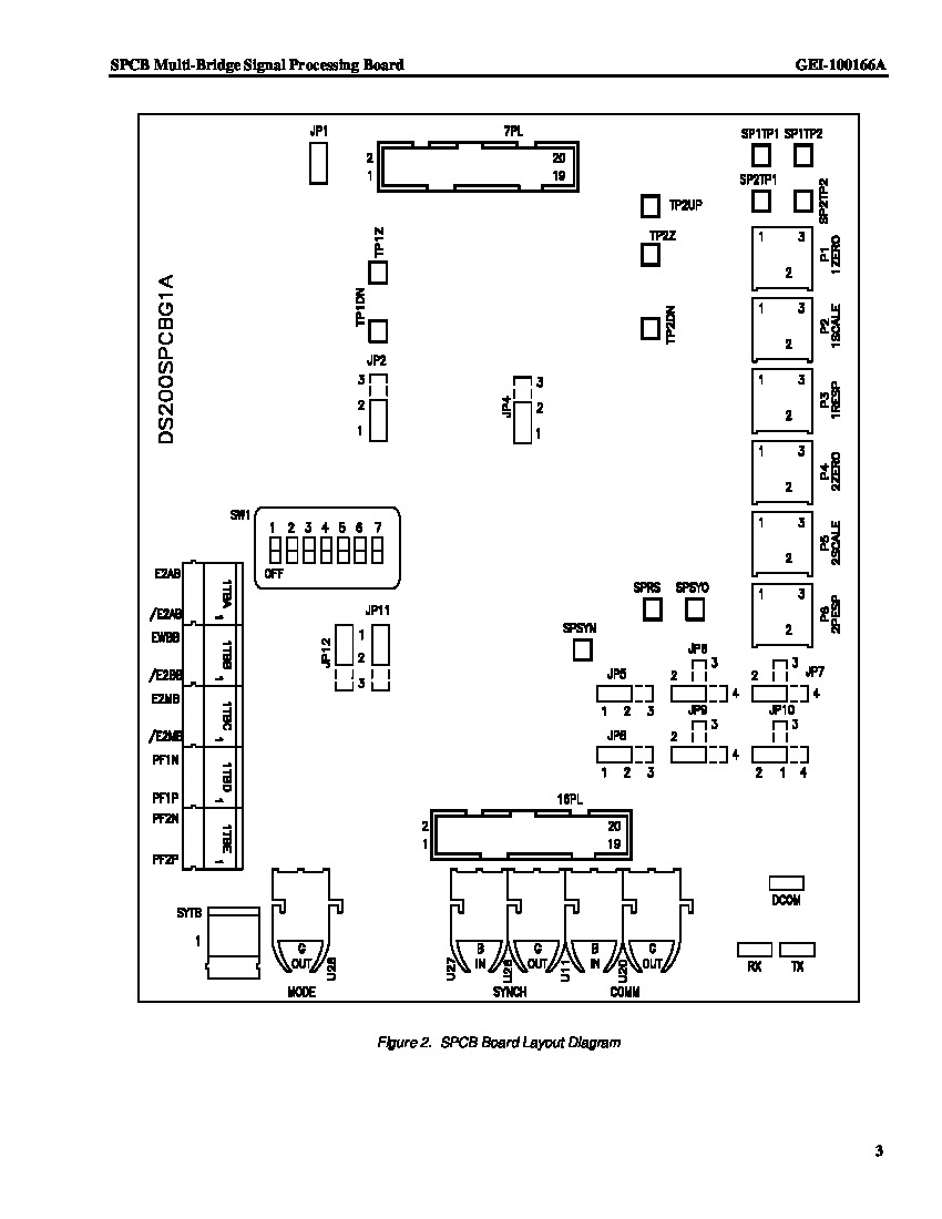
This DS200SPCBG1AAA Multi-Bridge Signal Processing Card necessitates a series of hardware components and specifications due to its intended Mark V Speedtronic Series functionality. The DS200SPCBG1AAA board is designed to create an interface between the multi-bridge hub comm board and the drive control board. This DS200SPCBG1AAA PCB has two encoder follower circuits, fiber-optic interface circuits, and two processor control (analog) interface circuits, and is commonly used to process encoder feedback, convert and transmit analog process control voltage signals, and to transmit and receive synchronization signals. The DS200SPCBG1AAA has:
- a switch with seven points
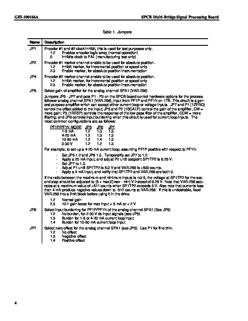
- twelve jumper switches located across the surface of the board
- a larger terminal board and a small terminal board
- as six potentiometers
These potentiometers can be adjusted from their original 12 o’clock position to optimize drive performance. Generally, potentiometers are used to provide zero and gain adjust, and to adjust the response of analog channel time.
Critical DS200SPCBG1AAA Connections
The DS200SPCBG1AAA board additionally features several fiber-optic connectors, single-pin connectors, and vertical (multi) pin connectors. Most components on the base circuit board of this DS200SPCBG1AAA Mark V Series product, including its various connectors, are marked with reference designations so they can be easily identified. Some of the specific connectors adopted into the assembly of this DS200SPCBG1AAA Multi-Bridge Signal Processing Card include but aren't limited to:
- The 11-pin E1UP Output Connector
- The 16-pin DCOM Power Supply Return Common Output Connector
- The 18-pin SPSYO Drive Control Board Output Connector
- The U11 and U20-location COMM bridge-to-bridge communications connectors
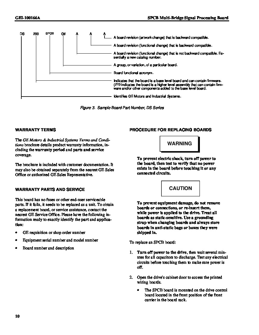
These are but a few of the many varied connectors utilized int the assembly of this DS200SPCBG1AAA Multi-Bridge Signal Processing Card that are outlined in original Mark V Series instructional manual documentation. The 15-pin 0RST7 Connector in the assembly of this Mark V Series product offering typically exists as a vestigial structure and goes unused during normative use of this DS200SPCBG1AAA PCB in the Mark V Series automated drive assembly. All of the components in the normal Mark V Series assembly attributed to this DS200SPCBG1AAA printed circuit board should receive some level of protection from the normal style of printed circuit board coating that has been applied to the base board of this General Electric product. Refer to GE manuals for additional information about the components as well as more information about handling, installation, and various jumper switch selections.


