About the DS200SDCCG1AGD
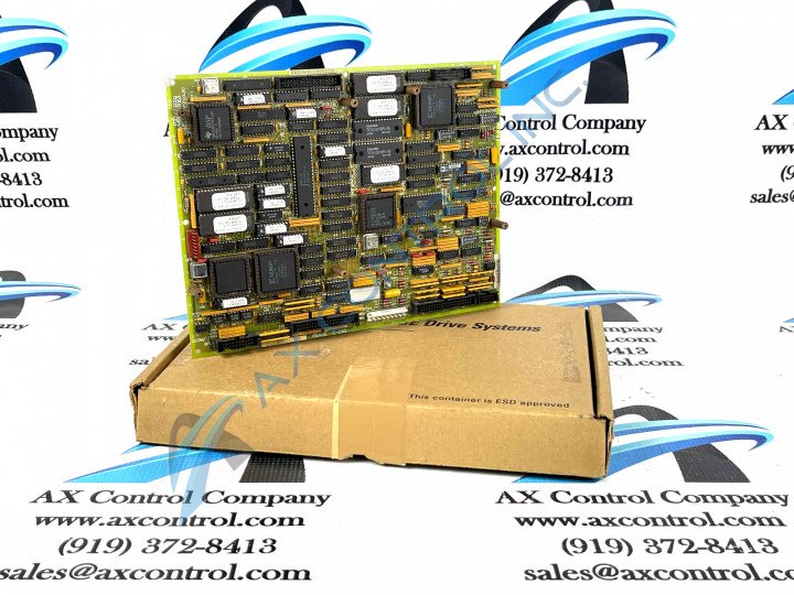
GE Drive Control Board DS200SDCCG1AGD is one of the primary controllers for the drive made for use in the Mark V series. The Mark V Series is one of the more recently-developed product series utilizing General Electric's patented style of Speedtronic technology in its assembly. This DS200SDCCG1AGD Drive Control Board's Mark V Series has specific applications in the management and control systems of relevant gas, steam, and wind turbines supporting General Electric products.
While this DS200SDCCG1AGD printed circuit board is definable as a Drive Control Board, its is by no means the original product with its specific functionality to exist within the Mark V Turbine Control System Series; that would be the DS200SDCCG1 Drive Control Board pointedly missing this DS200SDCCG1AGD product's three significant revisions.
Hardware Tips and Specifications
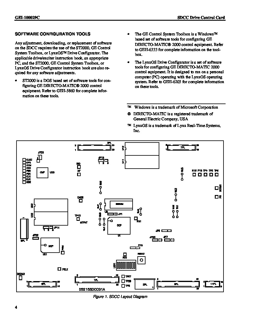
As with any product offered alongside the Mark V Turbine Control System Series, this DS200SDCCG1AGD PCB's assembly is populated by its own series of hardware components and component specifications introducing its intended series functionality. The GE Drive Control Board DS200SDCCG1AGD is populated with three microprocessors and RAM that can be accessed by multiple microprocessors at the same time.
Ten LEDs on the GE Drive Control Board DS200SDCCG1AGD are used to display fault codes if an error occurs that triggers a fault. These ten LEDs are arranged in a row and together will display the error code. If no error is encountered and the board is operating normally, the LEDs are lit in a sequence of two LEDs at a time from left to right. To view the LEDs on the DS200SDCCG1AGD, you can open the board cabinet door, locate the board, visually inspect the LEDs and understand the condition of the board. However, care must be taken when you open the board cabinet door because of the high voltage that exists in the boards and all components. Do not touch anything in the cabinet while the power is applied to the drive. Also, don’t let anything fall in the cabinet while the door is open, and close the door when the inspection is complete.
Several auxiliary boards within the Mark V Turbine Control System Series can be mounted on the face of this DS200SDCCG1AGD PCB, for added efficiency or processing functions. Some of these optional daughterboards include:
- The DS215SLCC or 531X306LCC LAN Communications Card
- The 531X309SPC Signal Processor Card
- The DS200SPCB Multibridge Signal Processor Card
All of these above products have been named through a combination of their alphanumeric product numbers and the functionality they play to the DS200SDCCG1AGD PCB and the rest of its Mark V Series automated drive assembly. When you first start the DS200SDCCG1AGD board after installing the product, you must set up the configuration parameters to define how the board will process information and control the drive. There are software tools available that enable you to edit the parameters, and are available for use on a laptop. If you have several units to configure at the same time, you can create one configuration and download the same configuration to multiple boards. For more information on the DS200SDCCG1AGD model, refer to the GEI-100029 Drive Control Card Manual attached above, which provides information on card groups, LED diagnostics, and more.


