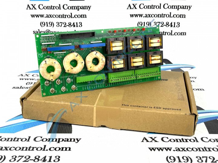
About the DS200PTCTG1BAA
This DS200PTCTG1BAA printed circuit board from General Electric was originally manufactured for use in the Mark V Turbine Control System Series. The Mark V Series that this DS200PTCTG1BAA product offering exists within has specific applications in the control and management systems of compatible wind, steam and gas turbine automated drive assemblies.
This DS200PTCTG1BAA printed circuit board or PCB for short is actually better-describable as a Potential Transformer Current Transformer based on its descriptions in Mark V Series instructional manual materials, although other fringe General Electric instructional documentation describes it as a Signal Conditioner Board.
While this DS200PTCTG1BAA product offering is a Potential Transformer Current Transformer in its own right, it is not considered the original product of this functionality to exist within the Mark V Series; that would be the DS200PTCTG1 parent Potential Transformer Current Transformer missing this DS200PTCTG1BAA product's three significant product revisions.
Hardware Tips and Specifications
This DS200PTCTG1BAA Potential Transformer Current Transformer makes use of both standardized Mark V Series hardware components and special DS200PTCTG1BAA functionality-introducing hardware components in its internal assembly. To truly contextualize this DS200PTCTG1BAA product offering's hardware elections, its full functionality must be explored. This DS200PTCTG1BAA Potential Transformer Current Transformer takes the PTs and CTs made available to the greater Mark V Series automated drive and scales and isolates their current signals and voltage signals, while simultaneously providing both auxiliary inputs and outputs for low voltage Mark V Series drive signals.
The TCCB Board also for sale here through AX Control plays a crucial functional role for this DS200PTCTG1BAA PCB; accepting secondary isolation transformers through use of this device's attached JKK connector. This DS200PTCTG1BAA Potential Transformer Current Transformer makes use of several various voltage-limiting hardware components in its assembly, including various Mark V Series rectifiers, capacitors, diodes, and integrated circuits. The GE Signal Conditioner Board DS200PTCTG1BAA features 1 terminal block with terminals for 72 signal wires. It also contains 1 50-pin connector.
The IDs for the terminals on the terminal block include:
- OUT2
- OUT1
- COM1
- COM2
- P15
- SO21
- L23
It also contains terminal posts for 6 signal wires. Before making a final purchase decision on this DS200PTCTG1BAA Potential Transformer Current Transformer, it is important to realize that its originally-indicated performance specifications and dimensions have been altered from their original statuses through its inclusion of a B-rated primary functional revision, an A-rated secondary functional revision, and an A-rated artwork configuration revision.
Due to the numerous signal cables that attach to the board, there is a risk of interference in the signals carried to and from the board. To reduce the risk, proper planning is important when you first install the drive, with several considerations to keep in mind as outlined in this DS200PTCTG1BAA product's original instructional manual. The interference in signals wires comes from power cables that supply power to the Mark V Series drive and other equipment in the surrounding area. The high-voltage power cables must be routed away from the signal cables if possible. To plan for this, bundle the power cables together and at the same time, attempt to bundle the signal cables together. If that is not possible try to limit the length at which the cables run in parallel. If the cables run in parallel for a greater length, keep the signal and power cable further apart. If the cable run in parallel for a lesser length, the cables can run closer together. One method to reduce interference on the DS200PTCTG1BAA Board and its related Mark V Series drive assembly is to run the signal and power cables at right angles to each other, which reduces the exposure of the signal cables to the interference. Under some conditions, shielded cables can be used to protect the signal wires from interference.


