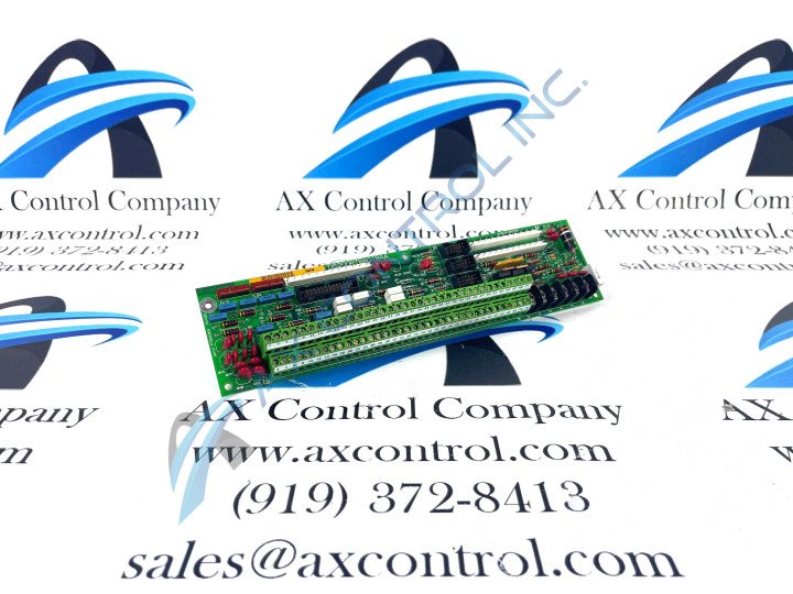
About the DS200PTBAG1BAA
The DS200PTBAG1BAA Protection Termination Module incorporates advanced protection algorithms and schemes to detect and respond to electrical faults promptly. It offers overcurrent, undervoltage, overvoltage, and reverse power protection, among other essential protection functions. This specific unit features:
- 2 terminal blocks with terminals for 72 signal wires in each
- 3 10-pin connectors
- various communication protocols
- serial ports
- Ethernet connectivity
- digital input/output channels
To enhance system reliability, the DS200PTBAG1BAA Protection Termination Board Assembly often incorporates redundant components and fault-tolerant features. Redundant power supplies, processors, and communication links ensure continuous operation even in the event of a component failure or communication loss. To connect a signal wire to a terminal post, first, obtain a flat-blade screwdriver and loosen the terminal screw. Insert the signal wire under the screw and tighten the screw.
DS200PTBAG1BAA Module Hardware
The DS200PTBAG1BAA module is designed to withstand harsh industrial environments. It is typically housed in a rugged enclosure with suitable environmental ratings, including temperature, humidity, and vibration resistance. The DS200PTBAG1BAA module operates on appropriate power supply voltages and incorporates electrical interfaces compatible with the control system and protected devices. This General Electric Mark V Series product additionally often includes diagnostic functions to aid in troubleshooting and maintenance activities. Built-in self-tests, event logs, and fault recording capabilities assist in processes such as:
- identifying and resolving issues efficiently
- minimizing downtime
- maximizing system availability
The DS200PTBAG1BAA module provides comprehensive configuration and monitoring capabilities, allowing operators to customize and fine-tune protection settings based on the specific requirements of the application. It typically includes software tools or a user interface for easy parameter adjustment and real-time monitoring of these aforementioned protection statuses and alarms.
DS200PTBAG1BAA Possible Connections
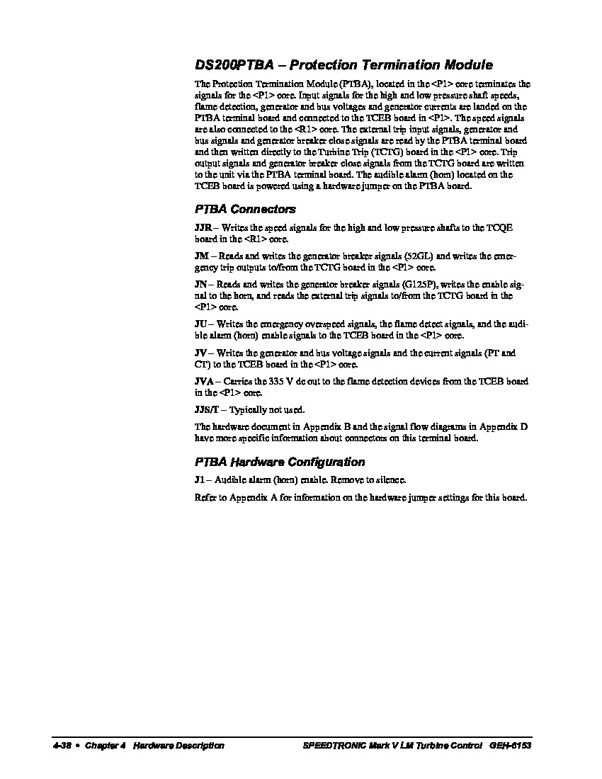
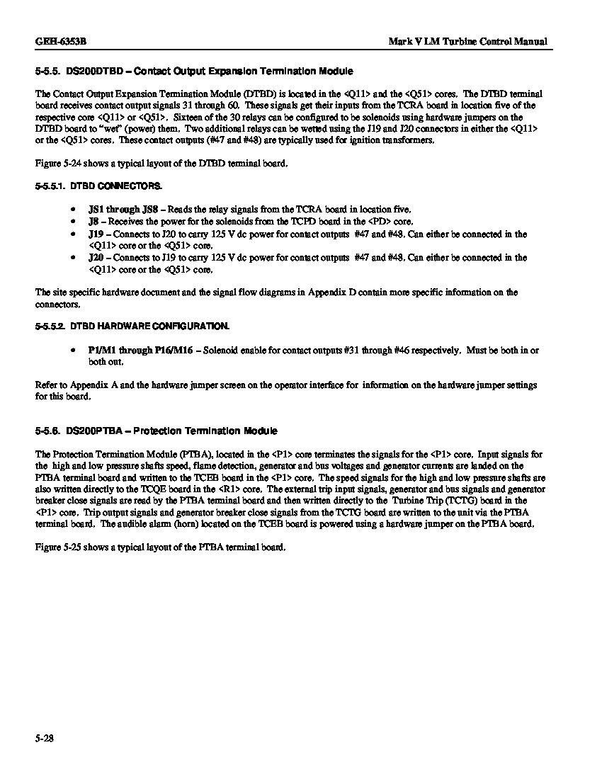
Some of the various connectors adopted into the assembly of this DS200PTBAG1BAA Protection Termination Module include:
- The JJR speed signal TCQE Connector
- The JM generator breaker signal TCTG Connector
- The JN external trip signal TCTG Connector
- The JU emergency overspeed signal TCEB Connector
- The JV bus voltage signal TCEB Connector
- The JVA flame detection device TCEB Connector
As the well-versed Mark V Circuit Board owner may recognize, all of these compatible connectors seem to feature the functional acronym of other boards from the Mark V Series; these all just represent different circuit boards within the Mark V Series that this DS200PTBAG1BAA Protection Termination Board can interface with. One more possible connector type to the assembly of this DS200PTBAG1BAA PCB is the JJS/T Connector, although that connector is typically not used and exists as a vestigial structure.


