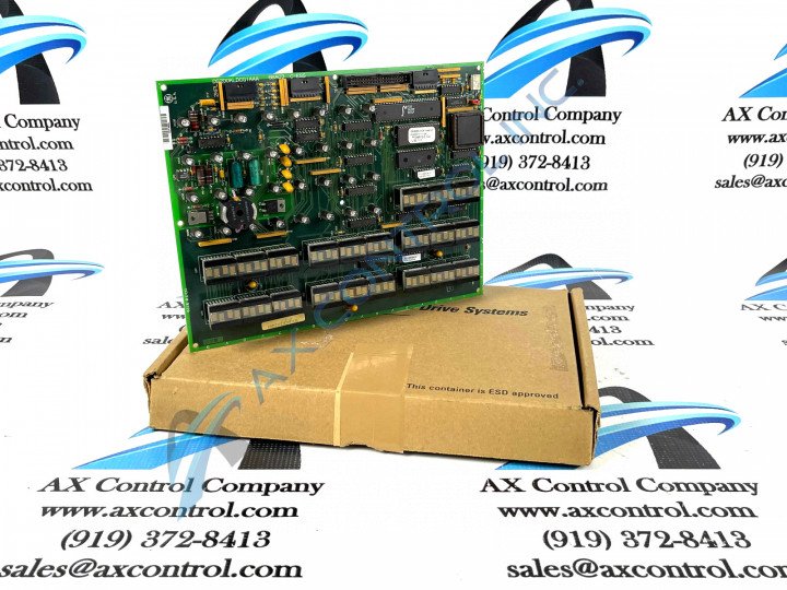
About the DS200KLDCG1
This DS200KLDCG1 printed circuit board product offering was originally manufactured by the trusted General Electric automated industrial retailer for specific application in their Mark V Turbine Control System Series. The Mark V Series that this DS200KLDCG1 printed circuit board belongs to has specific applications in the control and management systems of compatible wind, steam, and gas turbine automated drive assemblies.
Additionally, this DS200KLDCG1 product offering's greater Mark V Series is listed in original General Electric documentation as one of the final GE Mark product series to make use of their patented Speedtronic control system technology.
This DS200KLDCG1 printed circuit board or PCB for short happens to exist as the original product of its intended Mark V Series role, as evidenced by its DS200KLDCG1 functional product number's possession of no trailing, revision-indicating digits at the end.
Hardware Tips and Specifications
This DS200KLDCG1 printed circuit board's intended Mark V Series functionality is versatile, but not quite versatile enough to require any special form of Mark V Series assembly version. The GE Key/LED/Display Board DS200KLDCG1 features 32 LEDs, twenty-one 4-character displays, and one jumper. The GE Key/LED/Display Board DS200KLDCG1 also features one 40-pin connection strip on the rear of the board. The 4-character displays are used to show information concerning the operation of the drive and so are the 32 LEDs.
For that reason the board is installed in a location on the drive to make the board visible to the operator. The operator can use the information to maintain the operation of the drive.
This DS200KLDCG1 device's DS200KLDCG1 functional product number itself can be considered a good primary source of hardware component and component specification information. The DS200KLDCG1 functional product number codes for different DS200KLDCG1 Board basic specifications through the use of several consecutive functional naming chunks. For example, the DS200KLDCG1 functional product number begins with the dual-functional DS200 series tag delegating this DS200KLDCG1 PCB's normal Mark V Series assembly version and its domestic location of original manufacture. Some of the other critical hardware traits revealed in the DS200KLDCG1 functional product number include this DS200KLDCG1 Board's:
- KLDC functional product abbreviation
- Group one Mark V Series product grouping
- Normal PCB coating style
- Absence of any product revision
The board is 8.5 inches by 11 inches and it comes with holes in each of the four corners. To install the drive it is important to notice several factors about the board. First, notice where the original board is installed and notice if screws are used to attach it. Have on hand a screwdriver that will enable you to loosen and remove the screws. Also notice any cables attached to it. Attach to the cables a small strip of paper or a tag that identifies what connector the cable is attached to. The connectors all have an identifier associated with it and you should write down that identifier on the tag. Also notice what pins are covered on the jumper. Before you install the replacement, place the jumper over the same pins so that the board will be configured the same as the old board. Use the screwdriver to remove the four screws from the old board. Keep the four screws together and any washers that were also attached.


