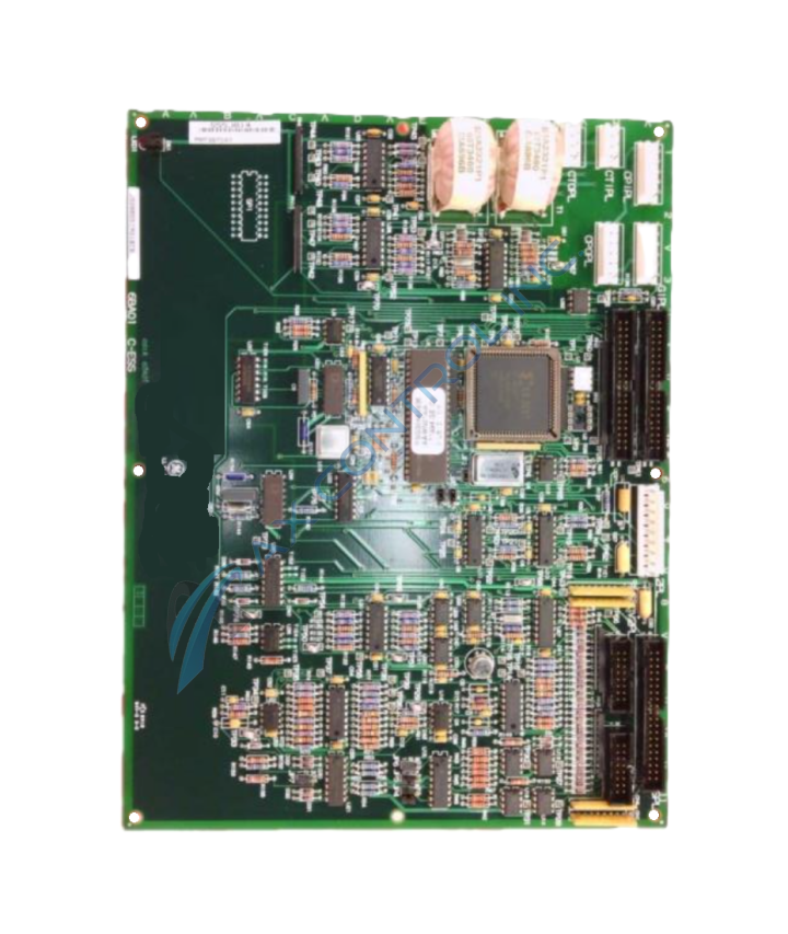
About the DS200GSIAG1BBB
As with any General Electric Mark V Series product offering, this DS200GSIAG1BBB Common Bus Regenerative Board necessitates its own particular series of hardware component inclusions and specifications. The GE Common DC Bus Regenerative Board DS200GSIAG1BBB contains:
- three 40-pin connectors
- two 16-pin connectors
- 6 jumpers
- 1 8-pin connector
- multiple test points
- Normal style of PCB protective coating
- Group One Mark V Series grouping
- Full three-fold revision history
All the jumpers on the board are identified with a series of letters and numbers printed on the board. All jumper identifiers begin with the letters JP. For example, JP1, JP2, and JP3. The one LED on the board is identified through the help of the diagnostic label CR, whereas the DS200GSIAG1BBB board's various test point identifiers begin with the letters TP.
DS200GSIAG1BBB Test Point Diagnostics
The test points are useful when the board is not behaving as expected and a servicer is attempting to pinpoint the defective circuit. The board must be removed from the drive to use the test points.
- One method is to install a replacement board in the drive and if the problem is resolved, you know the board is defective
- Use the test points to test the circuits and components on the board and if possible, have the board repaired. In that way, you have a readily available replacement board, if a replacement board is required.
Original General Electric instructional materials detail the testing process of this static-sensitive Mark V Series printed circuit board. To begin the diagnostic testing process, place the board on a flat surface with a static protective surface under the board. The test points are bare metal spears that you connect to a tester, or touch with a probe. Before attempting a test, make sure the probe is compatible with the testing device and is functional, and that the tester is calibrated correctly and that the controls on the device are set for the test being performed.


