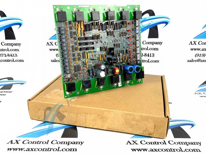
About the DS200FCRRG1AKD
As with any General Electric printed circuit board product offering, this DS200FCRRG1AKD PCB makes use of its own specific series of hardware component inclusions and specifications to gain its intended series functionality. The GE Firing Circuit Control Board DS200FCRRG1AKD features:
- 1 terminal block with terminals for 95 signal wires
- 10 2-pin connectors
- 2 ribbon cables
- a programmable logic device
The IDs of the 10 2-pin connectors begin with a numerical value and end with PL. The numbers are assigned in sequence and are printed on the surface of the board for easy reference by the installer or servicer. For example, some of the IDs are 1PL, 5PL, 12PL, and 15PL. Alongside some of the more specialized DS200FCRRG1AKD hardware component elements exist many of the Mark V Series-standardized voltage-limiting hardware components, including various capacitors, resistors, diodes, and integrated circuits.
DS200FCRRG1AKD Personalized Product Installation
Before making a final purchase decision on this DS200FCRRG1AKD printed circuit board, it is crucial to realize that its originally-introduced performance specifications and dimensions have no doubt been impacted through its possession of a full, three-fold product revision history. This DS200FCRRG1AKD Firing Circuit Control Board is offered alongside a slew of pertinent installation and replacement guidelines, given its attribution as a static-sensitive printed circuit board:
- Because of the number of 2-pin cables attached to the connectors, it is important to record where the cables are attached before you disconnect them
- If you connect the 2-pin cables to the wrong connectors, you might not realize the error until you attempt to start the drive
- To remove signal wires from the terminal block:
- have on a hand a narrow flat blade screwdriver
- loosen the retention screw and pull out the signal wire
- make sure the signal wire has about 0.5 inches of insulation removed from the end of the wire
- have all the bare wire inserted into the terminal
- if less than 0.5 inches of insulation is removed, the connection might not be made between the terminal and the signal wire


