About the DS200DTBDG1ABB
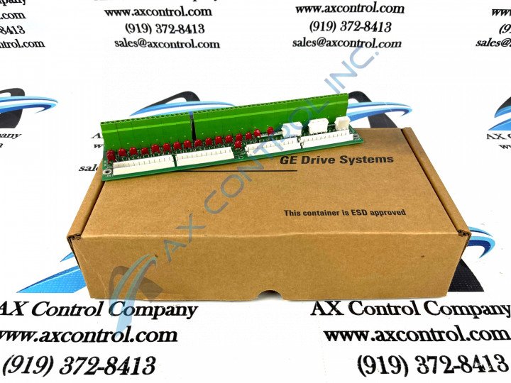
This DS200DTBDG1ABB product offering is accompanied by its own set of functionality-introducing hardware component inclusions, specifications, and installation procedures.The GE Terminal Board DS200DTBDG1ABB features 2 terminal blocks. Each block contains 107 terminals for signal wires. The GE Terminal Board DS200DTBDG1ABB also contains:
- multiple test points
- 2 jumpers
- 3 34-pin connectors
- 3 40-pin connectors
In addition to some of its more-specialized hardware component inclusions and specifications, this DS200DTBDG1ABB PCB is also populated by many standard Mark V Series voltage-limiting hardware components, such as rectifiers, diodes, and capacitors, and is additionally coated by a thick rudimentary protective layer of normal-style PCB coating. The board is 11.25 inches in length and 3 inches in height. It is designed to fit in a specific location in the drive interior and is secured in place with screws.
DS200DTBDG1ABB Connections
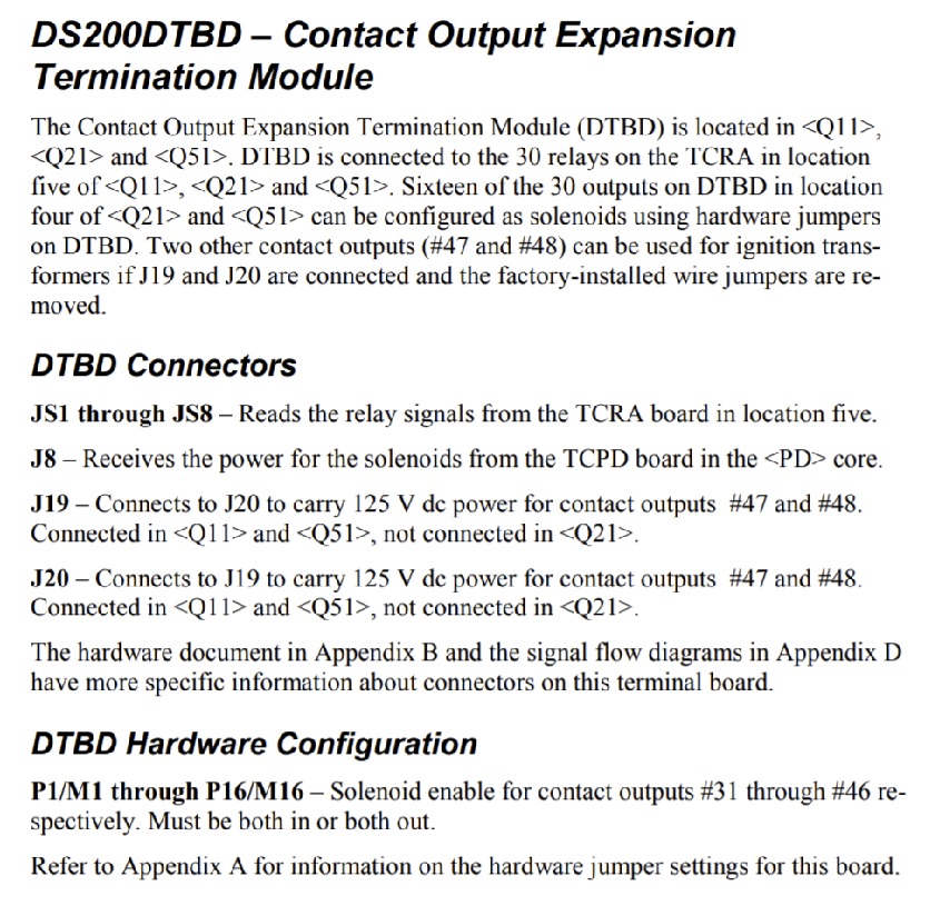
The connectors available to the assembly of this DS200DTBDG1ABB product offering include:
- The JS1-JS8 TCRA Board Relay Signal Connectors
- The J8 TCPD Board Solenoid Power Connector
- The J19 and J20 Daisy-Chained Contact Outputs Power Connectors
All of these aforementioned connectors in the assembly of this DS200DTBDG1ABB product have been named through a combination of their factory-printed nomenclature labels, potential Mark V Series interfacing opportunities, and specific selection or application for the DS200DTBDG1ABB PCB and its greater Mark V Series automated drive assembly.
DS200DTBDG1ABB Installation
The DS200DTBDG1ABB is accompanied by an intensive and guided installation process:
- First use a screwdriver to remove the screws from the GE Terminal Board DS200DTBDG1ABB.
- After you have removed the signal wires, ribbon cables, and other cables the board can be removed easily.
- With one hand remove the screws and hold them with your other hand. If they drop into the drive, retrieve them before you continue. They might cause a high-voltage short between cables or components. It is possible for them also to become jammed in the powerful moving parts in the drive; this might cause damage to the motor or other components.
- Carefully remove the board and keep it from hitting against other boards or devices inside the drive. You might accidentally knock off components from other boards or scratch the surface of boards. If you label the signal wires and ribbon cables with the connector IDs of where they are to be connected, the installation of the board is easy.
- Due to the multiple cables connected to the board, route the cables so that they do not block the air vents. The air vents enable cool air to enter the drive and draw away heat from the components.


