About the DS200DPCAG1
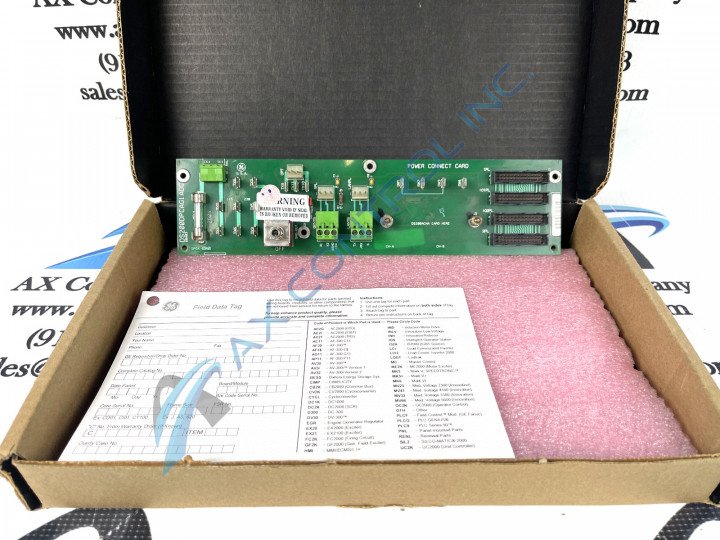
As specified in some sparsely-available General Electric instructional manual materials and the DS200DPCAG1 product description inserted above, this DS200DPCAG1 PCB is an IOS + Power Connect Board manufactured specifically for placement in the Mark V Turbine Control System Series. The Mark V Series that this DS200DPCAG1 PCB belongs to has specific applications in the management and control systems of popular and compatible wind, steam, and gas turbine automated drive assemblies.
This DS200DPCAG1 PCB's Mark V Series is somewhat desirable on the used automated industrial parts marketplace, as it exists as one of the final-developed General Electric product series to feature the patented Speedtronic control system technology.
Hardware Tips and Specifications
The GE IOS + Power Connect Board DS200DPCAG1 features 3 terminal blocks for 3 wires in each block and one toggle switch. The DS200DPCAG1 also features one fuse and four 26-pin connectors. The terminal blocks enable the installer to attach a maximum of 9 wires to the board.
To remove the wires during the replacement of the board, first note where each wire is attached on the terminal block. All the connectors have a unique identifier and you need to write on a label the identifier and attach it to the wire. Use a screwdriver to loosen the screws that hold the wire in the terminal. Remove the wire from the block.
This DS200DPCAG1 PCB is actually definable as the original product of its specific Mark V Series functional role, as the DS200DPCAG1 functional product number contains no trailing, revision-indicating alphanumeric digit.
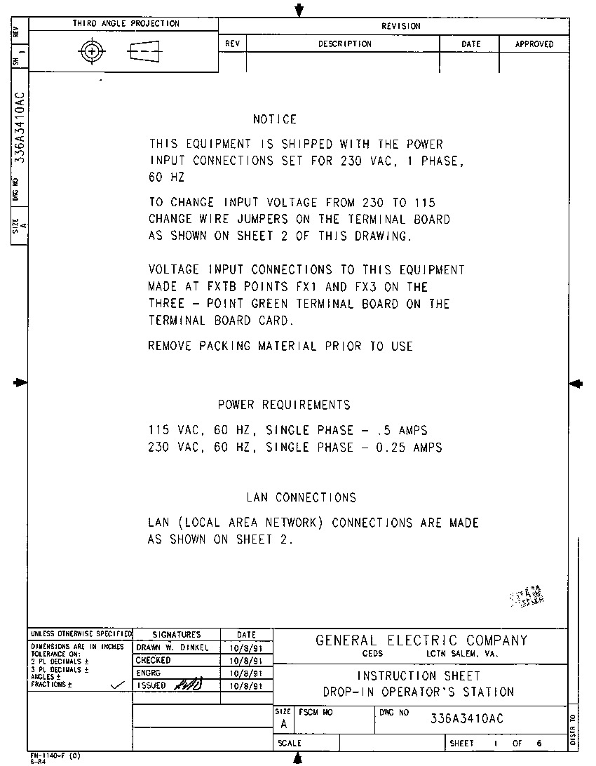
According to the DS200DPCAG1 Diagram attached in our convenient manuals tab above for your convenience, generally, this DS200DPCAG1 PCB is protected by a NEMA 4 protective chassis in its greater Mark V Series automated drive assembly.
Generally, this DS200DPCAG1 IOS + Power Connect Board's voltage suppression and limitation strategy involves its normal Mark V Series assembly's acceptance of a specific series of specialized voltage-limiting hardware components including:
- capacitors
- resistors
- transistors
- diodes
- specialized integrated circuits
Wear a static protective wrist strap when you work with the replacement board. The wrist drains away the static that accumulates on your body or the board. One end of the strap wraps around your wrist and the other clips to a metal surface that is not painted. To further prevent damage from static, keep the board in the protective bag until you are ready to install it in the drive. Another way to keep the danger of static at a minimum is to refrain from walking around with the board in your hands. Insert each wire into the terminal indicated on the label you created and while holding the wire in the terminal, tighten the screw to hold in place. Don’t over tighten the screws because it might damage the wire or damage the terminal block. The above-included information is disproportionately reminiscent of the installation or replacement of this DS200DPCAG1 PCB.
Given this lack of instructional research documentation, the DS200DPCAG1 functional product number itself can be considered a primary source of DS200DPCAG1 Board information; coding for specific details in a series of consecutive functional naming segments. For instance, the functional product number DS200DPCAG1 is started by the dual-functional DS200 series tag delegating this DS200DPCAG1 PCB's normal Mark V Series assembly as well as its domestic location of original PCB manufacture. Some of the other hardware details revealed in the DS200DPCAG1 functional product number include this IOS + Power Connect Board's:
- DPCA functional acronym
- Normal PCB coating style
- Group one Mark V Series product grouping


