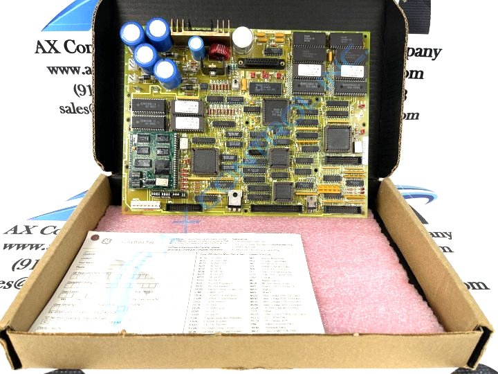
About the DS200DMCAG1A
The DS200DMCAG1A functions as an Interface board, and because of this specific Mark V Turbine Control System Series functionality; necessitates its own series of specific hardware component inclusions and specifications. This board has several connectors on its surface. These connectors include:
- three vertical pin header connectors
- four vertical pin male cable connectors
- one female cable connector
- several stab-on connectors are also used
Auxiliary GE Mark V DS200DMCAG1A Interface Board Hardware
The board is populated by multiple other components including:
- a reset switch
- two fuses
- seventeen resistor network arrays
- four LED banks with a varying number of LED lights per bank
- fifteen resistor network arrays
- a small auxiliary board with several integrated circuits
- two heat sinks
- over fifty integrated circuits
- six high voltage electrolytic capacitors
- smaller ceramic and polyester vinyl capacitors
- diodes
- an inductor coil
- transistors
A more detailed description of the board, its setup, and how to properly install it can be found within technical support publications from General Electric like user guides and manuals. Additional technical support products were supplied by GE with OEM purchases.


