DS200DCFBG1BLC

    Varying star amount pictures Varying star amount pictures Varying star amount pictures Varying star amount pictures Varying star amount pictures
  • 4.94 (17)
  • Click a star to rate this product
    Varying star amount pictures Varying star amount pictures Varying star amount pictures Varying star amount pictures Varying star amount pictures
  • 4.94 (17)
  • Click a star to rate this product
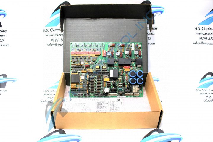
This DS200DCFBG1BLC DC Feedback Power Supply was manufactured for General Electric's Mark V Series of turbine control systems.

AVAILABILITY:

IN STOCK
SHIPS IN 3-5 DAYS

Sell Surplus: Have a DS200DCFBG1BLC to sell? Sell Now
Exchange Credit: Learn more about our exchange credit program
  • Part Number: DS200DCFBG1BLC
  • SKU: GBTC-11257
  • Manufacturer: GE Boards & Turbine Control
  • Series: Mark V DS200

DS200DCFBG1BLC Technical Specifications

Manufacturer GE General Electric
Series Mark V
Part Number DS200DCFBG1BLC
Functional Description DC Feedback Power Supply Board
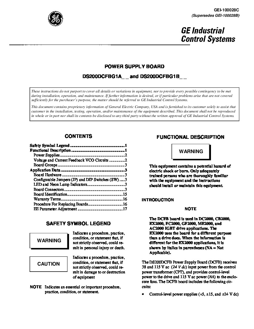
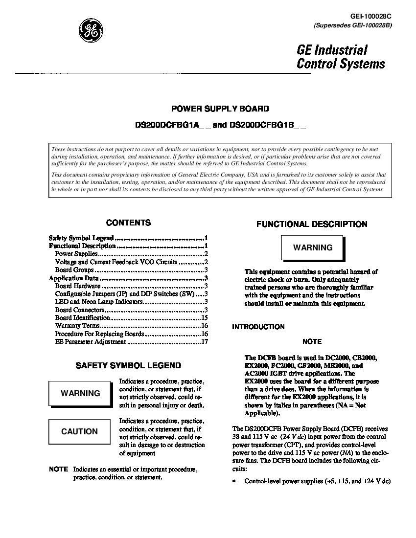
Instruction Manual GEI-100028
Functional Acronym DCFB
PCB Coating Normal Coating
Functional Revision 1 B
Functional Revision 2 L
Artwork Revision C
Weight 2 lb

About the DS200DCFBG1BLC


Overview of the General Electric DS200DCFBG1BLC Power Supply Board

  • The DS200DCFBG1BLC is a power supply board designed by General Electric for their Mark V series of optional and replacement boards.
  • This board is cross-compatible with various GE exciters and drives, including the DC2000, AC2000, CB2000, ME2000, and FC2000 series.
  • It provides system control level power to the installed drive and supplies electricity to the enclosure fan.
  • The board accepts sourced AC inputs ranging from 38 to 115 VAC, with accompanying frequencies from 0 to 500 kHz depending on the input voltage.
  • While it functions as a power supply board, the original Mark V Turbine Control System Series power supply board was the DS200DCFBG1, which lacks the three significant functional revisions present in the DS200DCFBG1BLC.
  • The broader Mark V Turbine Control System Series has specific applications in the management and control systems of wind, steam, and gas turbine automated drive assemblies.

Hardware Tips and Specifications

  • The DS200DCFBG1BLC features intricate circuit systems designed to power most of the drive. These include:
    • An AC and DC monitoring circuit
    • A control level supply circuit
    • A motor field power circuit
    • A driver circuit
  • Users can configure twelve jumpers and seven DIP switches on the board to meet specific external requirements.
  • Onboard indicators (two LEDs and one neon lamp) communicate board status and provide diagnostic information.
  • Three integrated protective fuses safeguard against significant interruptions or surges to the currents on the DS200DCFBG1BLC board and its associated Mark V Series automated drive assembly.
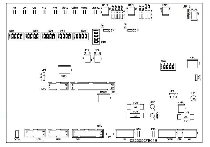
  • The board includes five test points for periodic voltage level monitoring. These test points are:
    • P5 +5 V dc Power Supply Testpoint
    • DCOM 0 V Test Signals Common Reference Point
    • P15 +15 V dc Power Supply Testpoint
    • N15 -15 V dc Power Supply Testpoint
    • ACCT DCFB to SDCC ACCT Signal Testpoint
  • The names of these test points reflect their factory-printed labels, voltage ratings, and functionality within the board and the Mark V Turbine Control System Series.
  • The DCFB and SDCC boards, which are accessed by the ACCT testpoint, are also available for purchase and repair in various revision styles.

Installation and Safety

  • It is imperative to follow the provided installation parameters for both the DS200DCFBG1BLC and the drive to ensure proper operation.
  • The DS200DCFBG1BLC printed circuit board should be handled as a static-sensitive product.
  • Be aware that potentially lethal surface voltages may exist on the board during or after normal functional use, even after the power is off.
  • For detailed wiring and installation guidance, refer to the series manual and the device datasheet.
  • General Electric originally provided technical support for all boards in the Mark V series.
  • For pricing and availability of the DS200DCFBG1BLC and other parts or repairs, you can contact AX Control by phone or email.

Frequently Asked Questions about DS200DCFBG1BLC

How much input power does DS200DCFBG1BLC receive from the CPT?
DS200DCFBG1BLC receieves 38 and 115 VAC (24 VDC) input power from the control power transformer (CPT) connected to DS200DCFBG1BLC.
Where can I find descriptions of the connector pins on DS200DCFBG1BLC?
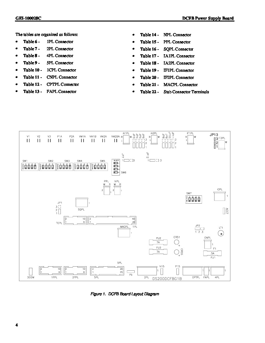
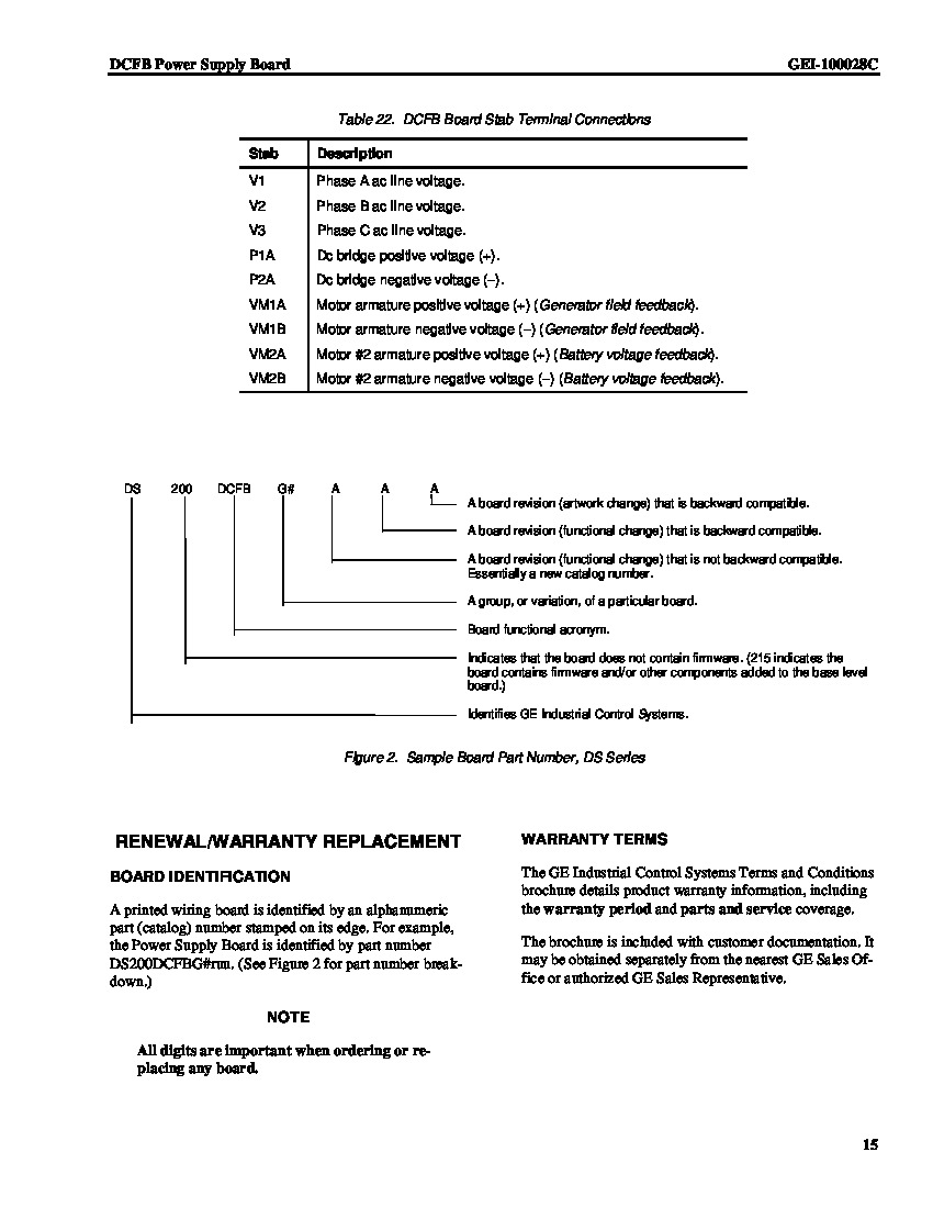
DS200DCFBG1BLC gets and sends input and output signals/power via 18 plug connectors and 9 stab connectors. Tables 6-22 in the manual for DS200DCFBG1BLC, Manual GEI-100028, provide descriptions for each of the connectors. The tables in the manual identify DS200DCFBG1BLC connectors by pin, nomenclature, and description. Figure 1 in the manual for DS200DCFBG1BLC, which is the GE Industrial Systems Power Supply Manual, also shows locations of the connectors via a DS200DCFBG1BLC board layout diagram.
How many jumpers does DS200DCFBG1BLC have?
DS200DCFBG1BLC has 12 configurable jumpers. For locations of the jumpers The jumpers on DS200DCFBG1BLC are jumpers JP1-JP14 but jumpers JP13 and JP14 have been deleted on DS200DCFBG1BLC. You can find locations of DS200DCFBG1BLC's jumpers in figure 1 in the manual and you can find descriptions of the jumpers on DS200DCFBG1BLC in table 1 of the manual - Manual GEI-100028. For a copy of the manual, request DS200DCFBG1BLC's manual.
What is stab P1A on a GE DS200DCFBG1BLC board?
Stab P1A on DS200DCFBG1BLC, one of DS200DCFBG1BLC's stab terminal connectors, is DS200DCFBG1BLC's connector for DC bridge positive voltage.

Reviews For DS200DCFBG1BLC

Internal Review
(5.0)

This board includes a relay (K2) that acts as a pilot relay for the MD contactor. The coil is driven by the SDCC/LDCC board via IPL-34, IPL-35 and IPL-36. JP2 (jumper 2) will decrease the AC contactor drop-out time for this relay from its normal operation (about 100 ms of delay) down to a minimum delay state. Before making a final purchase decision on this DS200DCFBG1BLC PCB, you must know that it is edited through three revisions. - AX Control Lead Technician

Repair Services For DS200DCFBG1BLC

Type Lead Time Price Action
Repair Service 1-2 weeks $1840

Our highly skilled technicians can repair your DS200DCFBG1BLC. All of our repairs come with a 3 Year AX Control Warranty. Please contact us for additional information about our repair process. To receive the repair pricing and lead time listed above please process your repair order via our website. The following repair options may be available upon request:

  • 48-72hr Rush Repair
  • Detailed Repair Reports
  • AX Control Certificate of Warranty

AX Control Warranty Info

All products we sell are backed by our unparalleled warranty. A warranty certificate will be provided with your order upon request.
All PLCs, HMIs, and Turbine Control Boards: 3 Years
All AC/DC and Servo Drives: 2 Years
All Motors: 1 Year
Learn More