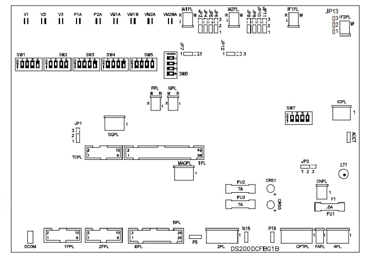
About the DS200DCFBG1BFB
The DS200DCFBG1BFB board supplies power to both the control level power and the enclosure fan. It receives sourced inputs from the control power transformer on the board, with nominal ratings between 38 and 115 VAC. The board outputs frequencies between 0 and 500 kHz, with rates dependent on the input voltage. Intricate circuitries on the board ensure proper operation, including:
- AC/DC monitoring
- Control level supply
- Motor field power
- Driver circuits
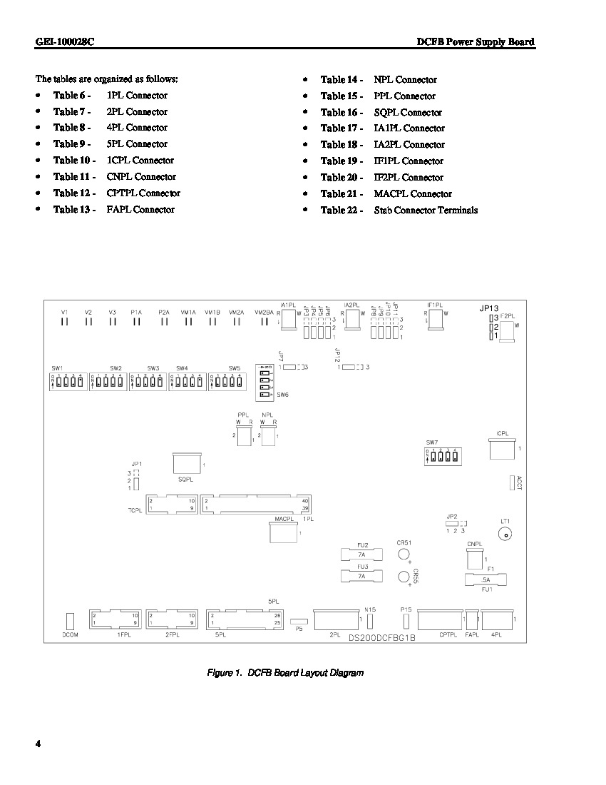
The DS200DCFBG1BFB offers configurable system options with twelve jumpers and seven DIP switches for user customization. Onboard status indicators (two LEDs and one neon lamp) provide diagnostic information about the board's fuses. Three integrated protective fuses safeguard against power supply interruptions. Five test points are included for periodically checking voltage levels on the board.
DS200DCFBG1BFB Safety, Installation, and Troubleshooting
- The board and the drive have specific safety and installation parameters that must be met to protect the overall unit.
- Illustrated installation and wiring guides are available in the device's manual and datasheet.
- General Electric originally provided technical support for both the DS200DCFBG1BFB and the Mark V series.
- Failure to follow original safety and installation parameters can lead to functional faults, potentially stopping the device's processes entirely.
- Functional faults in the assembly usually stem from a failure of one of its voltage-controlling fuses, indicated by one of the three LED indicators:
- CR5 LED (red) indicates a blown FU2 fuse.
- CR55 LED (red) indicates a blown FU3 fuse (pertinent to the -15 V dc regulator).
- LT1 neon lamp (external assembly) glows to indicate a failure of the FU1 fuse.
- All three fuses are typically protected by a normal PCB protective coating.
- AX Control offers sales and support for the DS200DCFBG1BFB and other automation needs, with current prices and availability accessible by phone or email.


