In Stock
DS200CPCAG1 Image One
3 year warranty

DS200CPCAG1 Image 1
DS200CPCAG1 Image 2
DS200CPCAG1 Image 3
DS200CPCAG1 Image 4

DS200CPCAG1

    Varying star amount pictures Varying star amount pictures Varying star amount pictures Varying star amount pictures Varying star amount pictures
  • 4.95 (19)
  • Click a star to rate this product
    Varying star amount pictures Varying star amount pictures Varying star amount pictures Varying star amount pictures Varying star amount pictures
  • 4.95 (19)
  • Click a star to rate this product
This DS200CPCAG1 PCB is a Contactor Pilot Card originally produced for General Electric's Mark V Turbine Control System Series.

AVAILABILITY:

IN STOCK
SHIPS TODAY

Sell Surplus: Have a DS200CPCAG1 to sell? Sell Now
Exchange Credit: Learn more about our exchange credit program
  • Part Number: DS200CPCAG1
  • SKU: DS200CPCAG1GBTC
  • Manufacturer: GE Boards & Turbine Control
  • Series: Mark V DS200

DS200CPCAG1 Technical Specifications

Manufacturer GE General Electric
Series Mark V
Part Number DS200CPCAG1
Functional Description Contactor Pilot Card
Functional Acronym CPCA
PCB Coating Normal Coating

Product Description

This DS200CPCAG1 General Electric printed circuit board is a Contactor Pilot Board that was originally developed for the Mark V Series of turbine control systems, as briefly explained above. This DS200CPCAG1 Contactor Pilot Board surprisingly exists as the original Contactor Pilot Board that was designed for placement within the Mark V Turbine Control Series, as evidenced by the apparent absence of any trailing digits at the end of its DS200CPCAG1 functional product number.

Hardware Tips and Specifications

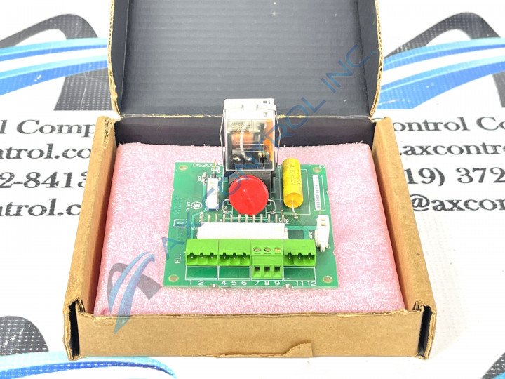
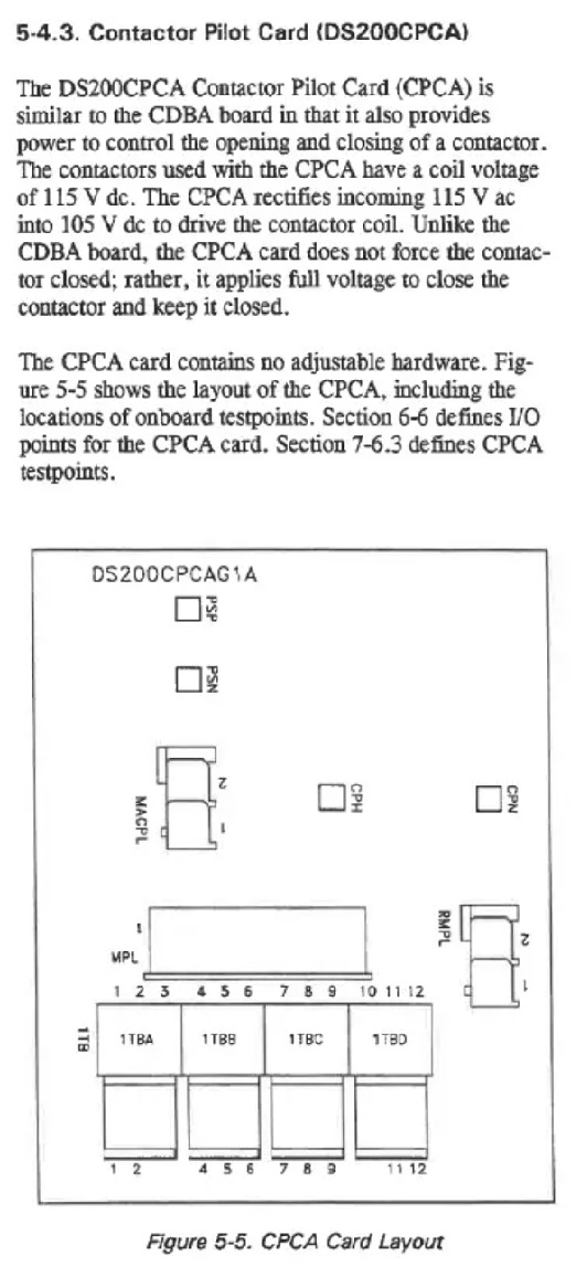
This DS200CPCAG1 Contactor Pilot Board is a Mark V Series product that adopts a standard number of hardware components and component specifications into its normal Mark V Series assembly and configuration. The  GE Contactor Pilot Board DS200CPCAG1 features one 12-pin connector, and two 2-pin connectors. It also features four terminal blocks to connect a maximum of twelve signal wires. The DS200CPCAG1 Contactor Pilot Board is also populated with a 24VDC socket power relay. When you are inserting the board into the drive cabinet and maneuvering it into position, make sure the relay doesn’t hit any metal structures or other components in the drive. The relay is a large component on the board and is sensitive to rough treatment and might be damaged. All of these mentioned hardware components should receive at least some basis of protection from the normal PCB coating style afforded to this DS200CPCAG1 product offering from General Electric. This CPCA-abbreviated printed circuit board additionally features a standard number of voltage-limiting hardware components, including diodes, capacitors, resistors, and integrated circuits, although no optional customizable hardware is available in this Mark V Series product offering's assembly.

The terminal blocks in the assembly of this DS200CPCAG1 PCB require some special consideration when you are replacing the board. Each terminal block can accommodate a maximum of three signal wires, and when you remove them it is vital that you install them in the right location on the new board. Original General Electric instructional manual materials instruct the prospective DS200CPCAG1 Board terminal block installer to attach to each wire a sticker, tape, or note with the terminal block identifier for the terminal the wire is attached to. From there, corrective activity involves using a small screwdriver to loosen the screw that secures the wire in the terminal, ensuring not to remove the screws entirely. When you are ready to reattach the wires, use a screwdriver to open the terminal block opening enough so the wires can fit inside. Press the wire into the terminal and tighten the screw over the wire. Use the identifier to know which terminal to attach the wire to. Make sure the wires are not liable to come loose but don’t tighten them so that the wires are damaged or the terminal screws are damaged.

Frequently Asked Questions about DS200CPCAG1

What type of film capacitor does DS200CPCAG1 have?
DS200CPCAG1 has a MFWA film capacitor. This means that DS200CPCAG1's capacitor is a 208 type film capacitor. This capacitor on DS200CPCAG1 is round, yellow in color, and located on the top left side of DS200CPCAG1.
How many hertz is DS200CPCAG1?
DS200CPCAG1 is  a 50/60Hz contactor pilot card.
How big is DS200CPCAG1?
DS200CPCAG1 is 4 by 3.5 inches.

Reviews For DS200CPCAG1

Internal Review
(5.0)

This DS200CPCAG1 Mark V Turbine Control Series printed circuit board is a Contactor Pilot Card designed with the Speedtronic technology introduced by respected retailer General Electric, as mentioned above. A bonus benefit of this DS200CPCAG1 PCB is that it exists as the original, base-revised version of the Mark V Series' Contactor Pilot Card. This CPCA-abbreviated PCB is a highly-connectable version of Mark V Series circuit board, and should be treated as a static-sensitive device during installation or replacement. - AX Control Lead Technician

Repair Services For DS200CPCAG1

Type Lead Time Price Action
Repair Service 1-2 weeks $225

Our highly skilled technicians can repair your DS200CPCAG1. All of our repairs come with a 3 Year AX Control Warranty. Please contact us for additional information about our repair process. To receive the repair pricing and lead time listed above please process your repair order via our website. The following repair options may be available upon request:

  • 48-72hr Rush Repair
  • Detailed Repair Reports
  • AX Control Certificate of Warranty

AX Control Warranty Info

All products we sell are backed by our unparalleled warranty. A warranty certificate will be provided with your order upon request.
All PLCs, HMIs, and Turbine Control Boards: 3 Years
All AC/DC and Servo Drives: 2 Years
All Motors: 1 Year
Learn More

DS200CPCAG1 Manuals, White Papers, Data Sheets, and Troubleshooting