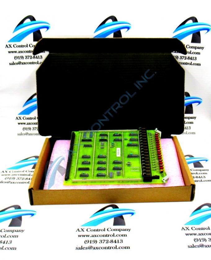
About the DS3800HLOA1E1C
This DS3800HLOA1E1C General Electric printed circuit board product offering was designed and produced specifically for the trusted automated retailer's Mark IV Turbine Control System Series. The Mark VI Turbine Control System Series that was soon to succeed this DS3800HLOA1E1C product's Mark IV Series represents a massive coming upgrade, as it expands the series' possible applications to alternative energy-geared wind turbine control and management systems.
Hardware Tips and Specifications
The GE Log Dr Bus Interface Board DS3800HLOA1E1C is designed for quick installation in the drive. The board features a modular connector on 1 end and retention levers on the other end. The GE Log Dr Bus Interface Board DS3800HLOA1E1C also is populated with 16 red indicator LEDs and 1 amber indicator LED which are visible from the front of the board. The board also features 8 jumpers and 1 erasable programmable read-only memory (EPROM) module.
One alternative source of DS3800HLOA1E1C Board hardware component and component specification information can actually be identified as its DS3800HLOA1E1C functional product number, which codes for a number of relevant DS3800HLOA1E1C Board details through a series of select GE-formulated functional naming components. For example, the DS3800HLOA1E1C functional product number begins with the dual-functional DS3800 series tag delegating this DS3800HLOA1E1C product's domestic original manufacture location and normal Mark IV Series assembly. Some of the other relevant hardware qualities revealed through analysis of the DS3800HLOA1E1C functional product number include this DS3800HLOA1E1C PCB's:
- HLOA functional product abbreviation
- Group one Mark IV Series product grouping
The GE Log Dr Bus Interface Board DS3800HLOA1E1C comes in a sealed plastic bag. The bag keeps static electricity from entering the board. Static is harmful to the board so it is best to keep the board in the bag. When you plan to install the board, only then should you slice open the bag with a sharp blade. Use 2 hands to remove the board and hold the board by the edges. Do not handle the components when you remove the board. You might accidentally press down on the components and bend them or cause them to break off the board. Align the board with the board rack and slide the board into the rack until the modular connectors meet. One modular connector is at the bottom of the rack. The other modular connector is embedded on the GE Log Dr Bus Interface Board DS3800HLOA1E1C. They are designed to fit together. Some of the connectors carry the current to power the board. Some of the connectors carry the command signals that are transmitted from the board. Others carry the signals that are received by the board for processing.


