Frequently Asked Questions about IS200EACFG2A
The IS200EACFG2A is a G2 version, how does it differ from a G1 version of the EACF boards?
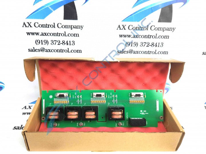
The G2 version of the EACF boards differs from the G1 version through its voltage range, it still supports a single three-phase input voltage but the nominal range should be 1000 VRMS at positive twenty percent at 50/60 Hz. Another way that the G2 version differs from the G1 version is that the G2 version has all transformers while the G1 version only has T3 and T2.
What is the secondary output voltage of the air core CT/flux coil inputs on the IS200EACFG2A board?
The output voltages from the air core CT/flux coil inputs typically read in the range of 0-0.8 VRMS at 50/60 Hz.
Does the IS200EACFG2A board need to be connected to another board? What are the connectors that allow for this to occur?
Yes the IS200EACFG2A board does need to be connected to another board. The standard connection is the EBKP backplane for the EMIO boards, to connect the IS200EACFG2A board to the EBKP backplane there are three nine-pin sub-D connectors labeled as J504, J509, and J514 that allow for this connection.
What are the corresponding terminal boards and their nomenclatures on the IS200EACFG2A model?
There are four terminals within the IS200EACFG2A board. TB1 is a PPT Phase A signal, TB2 is a PPT Phase B signal, TB3 is a PPT Phase C signal, and TB4 has a number of nomenclatures which are Coil1, high with terminal 1, Coil1, low with terminal 2, Coil2, high with terminal 3, and Coil2, low with terminal 4.


