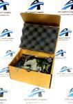
About the 193X737AAG01
The 193X737AAG01 is a GE PCB created as a component for the SCR Drive, the Speed Variator Drive, and other compatible systems. These are closed loop, adjustable speed systems run by a DC motor.
The 193X737AAG01 board functions as a Monitor board within the larger system. It is used to operate a fault relay, to detect fault conditions, and to indicate by an illuminated light in its front panel what fault condition has occurred. The 193X737AAG01 has four fault detecting circuits. The circuits indicate faults such as a blown fuse, overtemperature, overcurrent, and loss of phase. These circuits are designed as stated below:
-
Loss of phase: circuit is supplied from all three A.C. phases by means of tabs 7, 10, and 14. The other part of the circuit is a 120 volt DC supply to the indicator light, and to the output at tab 28 to supply the driver power on light.
-
Overcurrent: circuit operates on input to tab 29 from the static IOC circuit located on the driver coordination card.
-
Blown fuse: circuit operates on input to tab 3 from the fuse failure detector card.
-
Overtemperature: circuit operates from the opening of the circuit from tab 21 to common. This is normally kept closed by the thermostat located on the SCR conversion module.
The 193X737AAG01 is populated with an oscillator circuit board (193X738AAG01.) The main board also has carbon composite resistors and one large wire wound resistor (10W 250 10%.) It has eight capacitors that are normally made of polyester vinyl and may be mounted vertically.


