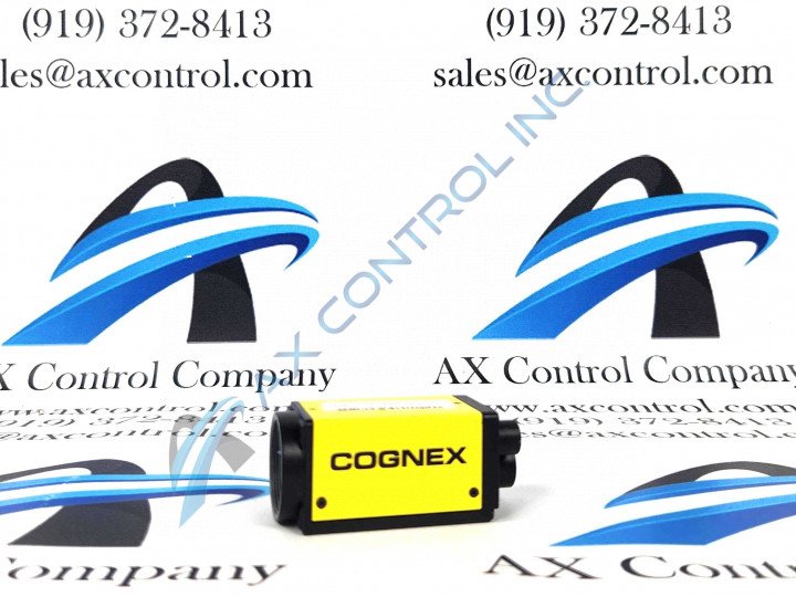
About the ISM1403-00
One key feature of the ISM1403-00 model is its ability to be used in factory settings, it can be used in applications regarding inspection, and specifically the review of items that could be scrapped or reworked. Allowing the ISM1403-00 model to inspect these types of items can help your company limit the amount of time and money it would take to discard and rework damaged parts. In relation to this model being used to inspect parts that have been damaged, it can also inspect larger models that could potentially have defects of some kind; it can also take precise measurements due to its high resolution which allows for greater accuracy reading of measurements and barcodes.
When you are installing the ISM1403-00 model please note that the wires and cables must be kept away from high-voltage power sources of wirings that are high-current, keeping these wires and cables away from the higher currents and voltages ensure that the risk of damage or malfunction is minimized. Some potential malfunctions and damages that could occur when the wires and cables are close to high-voltage power sources and high-current wires are power surges, line noise, over-voltage, and several others.
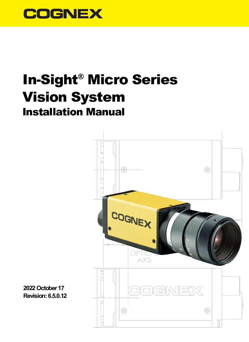
The three standard cables associated with the operation of this unit are Ethernet, I/O modules, and breakout cables. The I/O module and breakout cables each have five cable lengths whereas the Ethernet cable has six potential lengths as well as two different degree keys. All information regarding the cable lengths and degree keys can be found in the In-Sight Micro Series Vision System Installation Manual which was published in October 2022 above in the manuals tab of this page.


