Frequently Asked Questions about DS200SDCIG1AEB
What power supply circuits does DS200SDCIG1AEB have circuits for?
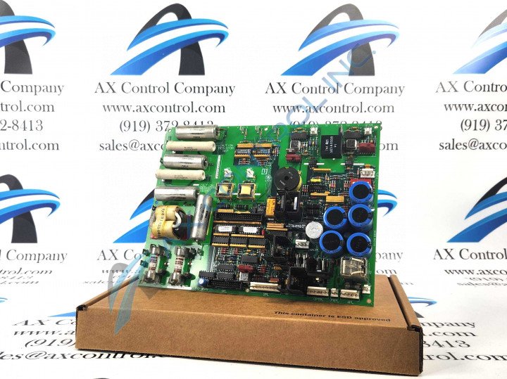
DS200SDCIG1AEB has circuits for power supplies: +5 VDC, 4A; +/-15 VDC, 0.4A; +/-24 VDC and 115 VAC, 0.4A.
What is covered in the manual for DS200SDCIG1AEB?
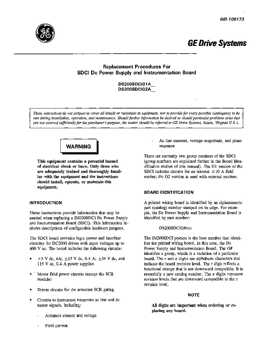
The manual for DS200SDCIG1AEB, Manual GEI-100173, the GE Drive Systems Replacement Procedures for SDCI DC Power Supply and Instrumentation Board Manual, provides instructions on the information needed when replacing a DS200SDCIG1AEB but also covers some other aspects of DS200SDCIG1AEB such as circuitry, jumpers, hardware, etc. The manual for DS200SDCIG1AEB does not cover everything about DS200SDCIG1AEB, and the manual should not be intended to provide every possible contingency during installation, operation, and maintenance of DS200SDCIG1AEB, but the manual will help greatly with DS200SDCIG1AEB.
What is fuse \"FU3\" used for on DS200SDCIG1AEB?
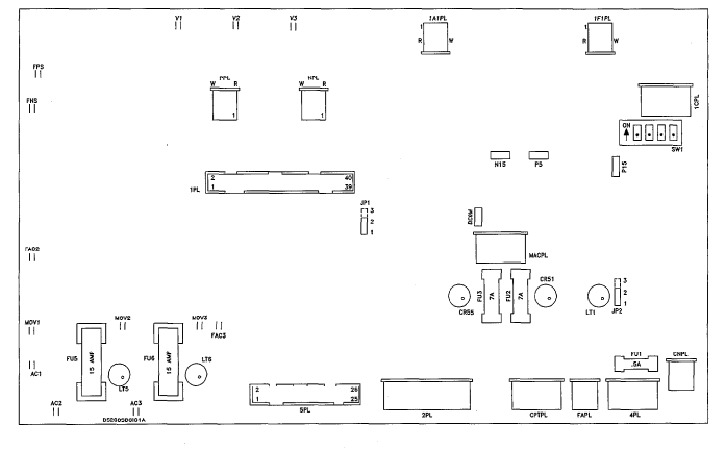
Fuse "FU3" on DS200SDCIG1AEB is the fuse for -24 and -5 VDC signal-level power supplies. If fuse "FU3" on DS200SDCIG1AEB is blown, the programmer is unable to display fault messages, but LED CR55 will be illuminated when control power is applied to the drive. When the "FU3" fuse is blown on DS200SDCIG1AEB, it's usually because of an accidental short of -24V, either while probing or due to a wiring error at the terminal board.
Which circuits on DS200SDCIG1AEB connect to AC line and DC motor signals?
Circuits to instrument numerous AC line and DC motor signals on DS200SDCIG1AEB include armature current and voltage, field current, AC line currents, voltage magnitude, and phase sequence.


