PID and Servo Tutorial

PID,  or Proportional-Integral-Derivative, is a control method used in industrial automation. This tutorial will clear up some misconceptions about this term.

PID controllers have been used in some form since the early 1900s.  They were originally based upon a 19th-century governor speed limiter.  Early PID-like controllers were used to automatically steer ships for the US Navy.  These controllers were developed by Nicolas Minorsky. He focused on designing a system that would provide stability against both small and large disturbances.

Today, nearly 95% of closed-loop industrial systems use PID control.

PID is essentially a feedback loop control made out of code. It can sometimes be made from the hardware.  PID, which stands for Proportional Integral Derivative, is made up of three separate parts that have been joined.  However, in some situations, all three parts of the control are not needed. As a result,  you can have P control, PD control, or PI control.

Explanation of PID Parts

  • P=Proportional. The proportional component of PID allows for the correction of a value in proportion to an expected error.  For example, if in building a system, you know your battery will slowly discharge and likely provide less power to your system, you can write a (P) value to correct for this known value error to control your output accordingly.
  • I=Integral.  The integral component of PID essentially takes up the slack left by (P.)  It is the running sum of previous errors.   What this means,  is whatever small amount of error left over after (P) is accounted for is taken care of by (I.)
  • D=Derivative.  The last bit of the PID code is supposed to predict the future.  The derivative component finds the difference between any current error and any previous error and adjusts the output accordingly.   Control loops that include a (D) component can significantly more time to ‘dial in’ due to the complex nature of the derivative.

PID frequencies are relative to the bandwidth of the servo or process, where the Integral term is most effective at low frequencies, Proportional at moderate frequencies, and Differential at higher frequencies.  PID is more common in process control where pressures, temperatures,  position, etc need to be optimally controlled.

The Effects of PID

In order to properly discuss the effects of PID, we must first look at a basic closed-loop servo and the equation for a closed-loop response.  In the Sept. 1990 issue of Motion Control, this block diagram of a basic servo and its response formula were published.

bode 1-1

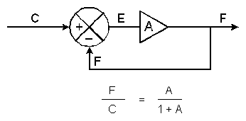
In the top diagram, we have the element (A).  The action of the summing junction is to subtract the feedback signal (F) from the input (C) with the result known as the error signal (E)=C-F.

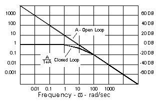
The Bode diagram (below)  shows how open-loop gain A in an amplifier/motor combination typically experiences a decrease of amplitude by a factor of 10 for every factor of 10 increase in frequency.

Bode 1

The net effect is that A is also A-90° since it has a gain factor of A and a phase lag of 90°. This closed-loop response [F/C = A/(1+A)]

As A’ approaches 1 on the Bode diagram (at 10 rad/sec in the example) the denominator becomes 1+1 -180°=1-1=0 and F/C becomes infinite.  As a result, severe oscillations can occur.   But in order to maintain a stable system, the denominator must not be allowed to approach zero.  A commonly accepted design goal is for A’ to have -135° of phase shift or less (45° of phase margin) This will result in a 25% overshoot of the closed-loop system in response to small step inputs.

As the phase margin gets larger, the amount and number of overshoots diminish.  In addition, as the phase margin gets smaller, the overshoots get larger and will “ring” for longer periods.  Finally, a sustained oscillation will occur.

Conclusion

PID provides phase compensation to improve the performance of the servo, using coding to create a closed-loop servo with a wider bandwidth and a greater gain (thus greater accuracy) within that bandwidth. If no velocity loop exists, PID is a good alternative.

Take a look at our current Woodward servo position controller stock for real-world examples of these machines.

Industrial Automation Terms You Should Know

Industrial Automation panel with digital technology and LEDs
Industrial Automation covers a lot of ground.

Here’s a list of industrial automation terms you may need to be defined as you’re looking at our extensive catalog of parts. 

A

AC (ALTERNATING CURRENT)

The commonly available electric power supplied, an AC generator and is distributed in single or three-phase forms. AC current changes its direction of flow (cycles).

AC MOTORS

A motor (see motor definition) operating on AC current that flows in either direction (AC current). There are two general types: induction, and Synchronous.

ACTIVE IRON

The amount of steel (iron) in the stator and rotor of a motor. Usually, the amount of active iron is increased or decreased by lengthening or shortening the rotor and stator (they are generally the same length).

AIR GAP

The space between the rotating (rotor) and stationary (stator) member in an electric motor.

AIR PRESSURE SWITCH

Used on motors with blowers to measure the difference in pressure across the filter so as to detect a clogged filter.

AIR TEMPERATURE SWITCH

A device used in air hooded motors to detect the temperature of the exhausted air. When used in this manner an air temperature switch will detect blockage in the cooling air system or long-term motor overload.

ALTITUDE

The atmospheric altitude (height above sea level) at which the motor will be operating; NEMA standards call for an altitude not exceeding 3,300 ft. (1,000 meters). As the altitude increases above 3,300 ft. and the air density decreases, the air stability to cool the motor decreases – for higher altitudes, higher grades of insulation or a motor derating are required. DC motors require special brushes for high altitudes.

AMBIENT TEMPERATURE

The temperature of the surrounding cooling medium, such as gas or liquid, which comes into contact with the heated parts of the motor. The cooling medium is usually the air surrounding the motor. The standard NEMA rating for ambient temperature is not to exceed 40ƒC.

ANTI-FRICTION BEARING

An anti-friction bearing is a bearing utilizing rolling elements between the stationary and rotating assemblies.

ARMATURE

The portion of the magnetic structure of a DC or universal motor which rotates

ARMATURE CURRENT, AMPS

Rated full load armature circuit current.

ARMATURE INDUCTANCE, MH

The armature inductance in milli-henries (saturated).

ARMATURE REACTION

The current that flows in the armature winding of a DC motor tends to produce magnetic flux in addition to that produced by the field current. This effect, which reduces the torque capacity, is called armature reaction and can affect the commutation and the magnitude of the motor’s generated voltage.

ARMATURE RESISTANCE, OHMS

The armature resistance is measured in ohms at 25ƒ C. (cold)

AXIAL THRUST

The force or loads that are applied to the motor shaft in a direction parallel to the axis of the shaft. (Such as from a fan or pump)

Coil Whine: Stop that Whining!

Let’s talk about coil whine.

Have you ever wondered why some of your electronics make noise, such as a low-level hum or a kind of squeal? If you have misophonia (a severe dislike or hatred of specific sounds) it might be the type of thing that drives you up a wall, even if it doesn’t register at all with your co-workers.

Close up of a power bar and an electric plug.  Coil whine begins in electromagnetic coils inside electronics.
Coil whine begins deep within your electrical components.

What causes coils to whine?

No, you’re not imagining the sound. It’s something called coil whine. The problem happens when the electrical current around the inductor coils in your computer increases beyond a certain point, causing them to vibrate and produce a sound similar to a boiling teapot located in a distant kitchen.

Coil whine happens because of AC power conversion. Components like transformers or inductors use electromagnetism to convert AC mains power to the DC power used by most electronics. If functioning properly, these switched-mode power supplies operate at a frequency well above human perception; however, a poorly designed or defective power supply may create a subharmonic frequency and produce noise as described above.

Other components can cause noise as well. Capacitors are also well known for ‘singing’ under certain conditions.

Is Coil Whine Dangerous?

While all this noise may be annoying, it’s not necessarily dangerous. However, since noise can sometimes be a sign of a defective load, it’s not a bad idea to test equipment that consistently emits any kind of unusual whine. You can also use thermal pads over the inductor coils to lessen the vibration causing the noise.

Please follow all proper safety procedures for your components, and always err on the side of caution when working on any kind of electronics: it’s better to ask for help than to risk injury!

For any kind of equipment repair, please feel free to contact us at 1-800-991-7026, or email us at sales@axcontrol.com.