
Surface mount technology has changed how printed circuit boards are designed. But what do you know about it?
The 1970s and 80s saw a sharp rise in the need for PCBs (printed circuit boards.) To meet that demand, designers had to find a way to manufacture boards more efficiently.
But the traditional way of mounting components–using pre-formed lead wires connected to the board through plated through holes–didn’t allow for fast assembly. Components had to line up at the correct angle before they could mount to the surface, slowing down assembly.
Enter surface mount technology. Originally called planar mounting, SMT was originally introduced in the 1960s, but didn’t become popular until the late 1980s. A decade later, most commercially developed PCBs used surface-mounted devices.
What Are the Advantages of SMT?
Surface mount technology has several advantages over previously used through-hole (TH) technology. These include
- easier assembly automation and repair
- improved electrical performance
- increased circuit density
- reduced manufacturing and handling costs
- higher overall product quality
SMT components take up less room than similar TH components. Also, unlike through-hole components, SMTs can mount to both sides of a printed circuit board.
What are the disadvantages of Surface Mount Technology?
However, surface mount technology has some drawbacks. Drawbacks are often related to the solder compound that connects components to the board and includes
- damaged connections caused by thermal cycling
- ultra-fine solder joint dimensions may have voiding that leads to joint failure
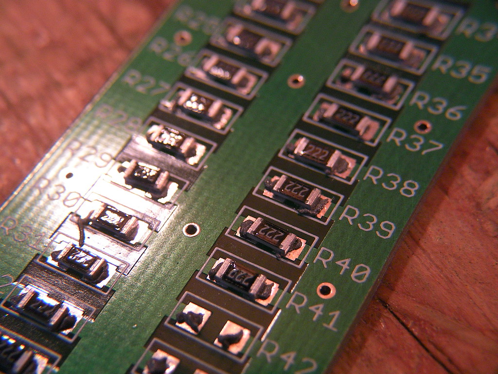
Other issues include cryptic ID codes due to lack of space on SMT components for identification marks, incompatibility with plug-in breadboards, and some incompatibility with sockets.
Also, surface mount boards may need additional support to protect from strain or flexing. Through-hole components naturally offer some flexibility; not so with those soldered directly to the board surface. Too much stress or warping and solder can crack. A good design can minimize this simply by mounting components at a right angle to the longest board dimension (the most likely to flex.)
SMT vs SMD: The Difference
As we’ve covered, Surface Mount Technology (SMT) is the method allowing electrical components to mount directly to the surface of a printed circuit board. So then, what is SMD?
A SMD, or Surface Mounted Device, is a component designed using surface mount technology (SMT) so it can mount directly to the board’s surface.
SMT equals technique. SMD equals doohickey. You’ll never forget it again.
How Does Surface Mount Technology Work?
SMT is a semi-automated process. Components are placed on top of a circuit panel and attached to copper pads, or traces, using solder.
Modern manufacturers often use pick and place machines to orient, locate, and place components. Solder paste is stenciled onto the board using a stencil printer before components are mounted. Using this method, manufacturers can mount tens of thousands of components each hour.
The boards have to be “cooked” in an oven in a final step to ensure the solder has made full contact between component and board.
Find out more about PCB components in our authoritative circuit board components blog post.
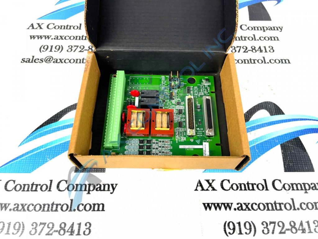
Need help sourcing replacement parts for GE, Reliance, or Woodward equipment? Our team can help with that!
You must be logged in to post a comment.