
What is a PCB?
A PCB, or printed circuit board, is one of the most fundamental components in electronics today. They are used in everything from everyday items like cell phones, computers, appliances, vehicles, and musical equipment to jets and nuclear power plants. PCBs allow electricity to travel between components across pathways etched into the surface of the board rather than use wires, allowing a significant simplification and reduction and size. Printed circuit boards have become so commonplace even the cheapest electronics now often have some sort of board component.
How Does a Printed Circuit Board Work ?
Printed circuit boards are essentially made from a sheet of copper plate sandwiched and laminated to sheets of a non-conductive substrate. Boards can have as many as sixteen layers and as few as one. Since the copper conducts energy and the substrate does not, this allows components on the surface of the board (like resistors, capacitors, or integrated circuits) to be connected to the conductive copper at specific points via solder points and then connected to each other via copper traces ‘drawn’ onto the copper sheet using acid. These pathways allow electricity to conduct between components.

How Do You Read a PCB?
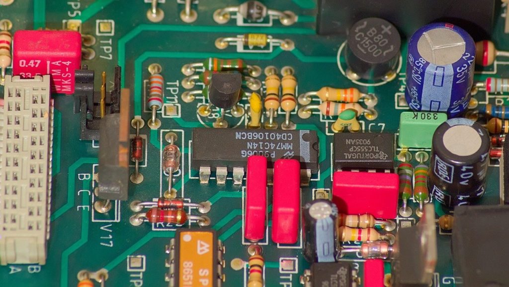
Most commercially made PCBs have been silkscreened with identifying text printed on their surface to help identify components and (possibly) the board use. For example, the board pictured above is part of the GE Speedtronic Mark VI turbine control system; the part number gives information about assembly location and type, module type, compliance, board technology, and compatibility.
The silkscreened codes added to the board’s surface allow surface-mounted components to be easily identified. For example, the board above has twenty-one integrated circuits marked U1 through U21. It also has capacitors (marked C), resistors (marked R), and diodes (marked D.) Some other commonly used codes include:
| F | Fuse | P | Plug | TP | Test Point |
| J | Jack /Connector | Q | Transistor | VR | Voltage Regulator |
| K | Relay | S | Switch | ||
| L | Coil Inductor | T | Transformer |
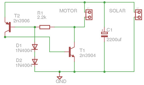
Additionally, boards are built upon a circuit diagram. This diagram acts as a blueprint. But just like a blueprint, you’ll get more information from it when you have already have a basis of knowledge to work from.
At the most basic level, a circuit diagram should give you an idea of how components interact as energy moves from one place to another on the board’s surface. You should have a basic understanding of what each type of component does, for example, that diodes only allow current to pass in one direction and that transistors amplify a charge.
If you’re ready to upgrade your equipment, contact us about selling your old PCBs or other equipment.
You must be logged in to post a comment.