
What is Ladder Logic? A Definition
Ladder logic stems from the history of relays. At one time, relays were the primary control for most automatic systems. These electromechanical devices consisted of coils and contacts that they moved. Energized coils moved their contacts from their resting position to their active position (either closed to open or open to closed.)

In practical application, a ladder diagram showed how to wire relays together. This diagram looked like a drawing of a standard household ladder with uprights and rungs. Modern-day ladder logic still follows these conventions. Relays did (and still do) their job well, but can be cumbersome due to the sheer size of multiple relays wired together. This is where programmable logic controllers using ladder logic can be advantageous: able to do the same kind of job but in significantly less space.
Differences Between Relays and PLCs
This is not to say that relays and PLCs are the same thing.
A relay acts as an electrically operated switch. These internal switches (otherwise known as contacts) operate via internal electromagnets or coils. The contacts can be “normally open” (N.O) or “normally closed” (N.C.); activating the mechanism through power application will switch them to their opposite setting. In other words, N.O contacts will close and N.C contacts will open.
A PLC, on the other hand, is a ruggedized computer specifically designed for industrial applications. Like your home computer, it can receive information from connected input devices, process data, and create outputs depending on specific parameters.
Like these early ladder diagrams, ladder logic still places power information at the top of the drawing and has the power (or hot) rail going down its left side. The right side holds neutral rail information. Then contacts go on the left side of the drawing, while outputs go on the right. Each output has its own ladder rung. A horizontal line represents a rung.
Is Ladder Logic Still Used?
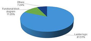
Yes. According to one 2016 study by Technavio, ladder logic continues as the dominant language for PLC programming–accounting for more than 81% of the global market–although some PLCs use instruction list programming, function blocks, structured text, or sequential function blocks. However, ladder logic remains popular and common.
Ladder Logic is Easy
One reason for ladder logic’s continued use is its simplicity. Since it reads left to right like most Indo-European languages, it’s easy to learn. When deployed, it executes from top to bottom and mimics electrical circuits, making it easy to troubleshoot.
One caveat for this continued popularity may be the slow transition from PLCs to PACs within industrial settings. PLCs (programmable logic controllers) have been around for decades. Newer PACs, or programmable automation controllers, offer the same essential functions and are used for generally the same things, but are typically programmed using C or C++. However, the jury is still out on whether PACs will be fully embraced by the manufacturing community as a replacement for reliable PLCs.
How to Read Diagrams
Ladder logic reads like the text in a book: left to right and top to bottom. Power in a ladder logic diagram flows left to right, and instructions descend from the top of the ladder to the bottom. Based upon electrical diagrams of relay logic, it’s easy to see why these diagrams were called ladders; the diagrams resemble an upright ladder with two vertical rails and several rungs between.
What Can This Logic Actually Do?
Ladder logic is most often used in the development of software for industrial programmable logic controllers (PLCs). Ladder logic creates a central architecture. This connects to function blocks holding more complex instructions. This type of structure allows for ease of programming while instructions become more complex. By using ladder logic, PLCs can:
- Have counting functions (count down/count up) to decrease or increase values on each transition of the input
- Make comparisons to determine if values are greater than, less than, or equal
- Have timing instructions for on- or off-delayed events.
- Include special functions like PID loops, shift registers, communication instructions, ramp generators, etc.
- Use math instructions for everything from addition and subtraction to finding square roots and changing the sign of a piece of data.
- Use Boolean expressions like “AND”, “NOT”, and “OR.”
Does Ladder Logic have Any Drawbacks?
All programming languages have their strengths and weaknesses. Ladder logic is no different. Even though it remains easy to use, the language cannot encapsulate code for reuse. This can make programs unreasonably long. Additionally, since ladder diagrams read and write to variables anywhere in the program in single memory bits, data can be difficult to protect or group. Finally, ladder logic can have difficulty with complex algorithms that involve a large number of variables.
How do I Learn Ladder Logic?
Nowadays there are literally thousands of free resources on the web for learning this programming language. Start by checking out videos on YouTube or on PLC supplier sites (Siemens, Allen Bradley, Omron) for training courses. You can also try this search string in Google:
site:edu ladder logic mooc
which should result in an additional resource list of previous Massive Online Open Courses. Closed courses may still have class notes, videos, or other resources available.
Have questions about the right PLC for your application? Talk to our staff today. We can help.
AX Control, Inc is a leading supplier of industrial automation parts to companies around the world. If you need help with drives, motors, circuit boards, turbine parts, or vision systems, talk to our team or take a look at our online inventory. We ship globally from our facility located in the heart of North Carolina.
You must be logged in to post a comment.